Today, an SoC can have multiple instances of an IP and also instances of many different IPs from different vendors. Every instance of an IP can work in a separate mode and requires a dedicated power arrangement which may only be formalized at the implementation stage. The power intent, if specified earlier, will need to be re-generated according to the target technology. Now imagine defining the power intent for a large number of IPs, sourced from multiple vendors, at the implementation stage; it’s nearly impossible and can be a nightmare for verification and debugging. The power intent needs to be specified in a top-down manner and refined from abstract at the top level to detail at the implementation level.
There was a technical paper presented by ARMand Mentor Graphicsat DVCon this year, which illustrates a very effective and efficient methodology for specifying power intent incrementally and refining it successively from abstract to implementation level.

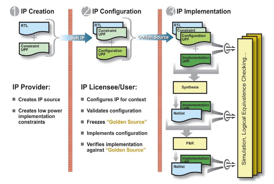
The successive refinement methodology employs three stages of an IP. The power intent for the IP at each stage is specified in an UPF (Unified Power Format) file at an appropriate level according to a strategy for successive refinement of the power intent.
The first stage is the IP Creation Stage when the most abstract view of the power intent is created by the IP provider. This abstract view is represented in a Constraint UPF file that contains the constraints on the power intent of the design (RTL). The power domain is defined at the ‘atomic’ level which cannot be further partitioned by the IP consumer. If the user intends to use retention in her/his power management scheme, then she/he must specify about the ‘retention constraints’ in terms of state elements to be retained.
Similarly, the Constraint UPF file should specify the ‘isolation constraints’ in terms of isolation clamp values that must be used if the user decides to shut down portions of the system as part of the power management scheme. Also fundamental power states of an IP block and its component domains should be defined in a technology-independent manner, i.e. without any reference to voltage levels. The ‘power states’ should be defined without any imposition on the IP consumer about the power management approach to be used. The Constraint UPF file should not be replaced or changed by the IP consumer.
The second stage is the IP Configuration Stage when the IP licensee or end user describes application-specific configuration of the UPF constraints in a Configuration UPF file. The Configuration UPF file contains details of the power management scheme for the system including design ports that a design may use to control power management logic, isolation and retention strategies on power domains along with their control logic, logic expressions on power domain states to reflect control inputs, and so on. The logical control signals may include signals for isolation and retention cells, and signals that will eventually control power switches when they are defined as part of implementation. The Configuration UPF file is required for simulation.
The third stage is the IP Implementation Stage when the end user describes technology-specific implementation of the UPF configuration in an Implementation UPF file. The Implementation UPF file contains details of the implementation such as power switches and voltage rails (i.e. supply network). It defines which supply nets specified by the implementation engineer are connected to the supply sets defined for each power domain. The technology references such as voltage values and cell references are part of Implementation UPF.
This scheme is well structured where power intent defined in constraint and configuration UPF files can be applied to different implementations that differ in technology details. The Configuration UPF loads in the Constraint UPF for each IP so that the tools can check that the constraints are met in the configuration. After that the Implementation UPF is added to specify implementation details and technology mapping. The complete UPF then drives the implementation process.
The Configuration UPF file for a system together with the Constraint UPF files for IP components and the RTL for the system and its components can be verified in simulation. Once verified, these files can be considered as ‘Golden Reference’ for the design cycle.
This approach enables the verification equity of the design to be preserved and relied upon through the implementation stages, thus shortening the design cycle. The full value of the approach can be realized when all elements are available in the entire tool chain.
Recently there was a press releasefrom Mentor in which they announced about IEEE1801 UPF 2.1 support in Questa Power Aware Simulation which completely supports this successive refinement methodology for power and accelerates the design and verification of power management architecture. The methodology of partitioning power intent into constraints, configuration and detailed implementation also simplifies debugging power management issues. For tools that do not yet support UPF 2.1, the Questa Power Aware can generate functionally equivalent UPF 1.0 from UPF 2.1 for them to support UPF-based flows.
A more detailed description of the methodology along with an example processor design is given in the DVCon paperjointly presented by ARM and Mentor.
Pawan Kumar Fangaria
Founder & President at www.fangarias.com


Comments
There are no comments yet.
You must register or log in to view/post comments.