PCB designers can perform pre-route simulations, follow layout and routing rules, hope for the best from their prototype fab, and yet design errors cause respins which delays the project schedule. Just because post-route analysis is time consuming doesn’t mean that it should be avoided. Serial links are found in many PCB designs, and doing post-route verification will ensure proper operation with no surprises, yet there is reluctance to commit signal integrity experts to verify all the links. I read a recent white paper from Siemens that offers some relief.
Here are four typical methods for PCB design teams to analyze designs after layout.
- Send PCB to fab while following guidelines and expect it to work.
- Perform visual inspection of the layout to find errors.
- Ask a signal integrity expert to analyze the PCB.
- Have a signal integrity consultant analyze the PCB.
These methods are error prone, time consuming and therefore risky. There must be a better way to validate every serial link to ensure protocol compliance prior to fabrication in a timely manner by using some clever automation.
Post-route Verification of serial links
Validating serial links is a process of electromagnetic modeling, analysis, and results processing. High signal frequencies used with serial channels require a full-wave electromagnetic solver to model the intricacies where the signals change layers, going from device pin to device pin. Analysis looks at the channel model including the transmitter (Tx) and receiver (Rx) devices, and the channel protocol to understand what the signal looks like at the link end. Results processing helps to measure if our design passes and the specific margins.
Channel Modeling
With the cut-and-stitch approach the channel is cut into regions of transverse electromagnetic mode (TEM) and non-TEM propagation, solving each region independently, and stitch each region together to create the full channel. Cut-and-stitch is less accurate than modeling the full channel at once, yet it’s a faster approach worth taking. Knowing where to make each cut is critical for accuracy and each cut region needs to include the discontinuity like a via, any traces nearby and the signal’s return path. An experienced SI engineer knows where to make these cuts.
The clever automation comes in the form of HyperLynx from Siemens, as it knows where to cut and then automatically create signal ports and setting up the solver for you. HyperLynx users can setup hundreds of areas per hour for full-wave simulations. To speed up run times the simulations can be run in parallel across many computers. On stitching, HyperLynx automates by adding lossy transmission lines with solved models. The length of transmission lines are adjusted, because parts of the signal trace are inside 3D areas. HyperLynx also automates each transmission line adjustments. You now can have interconnect models for hundreds of signal channels, by using automation and get the simulation results overnight.
Analysis
IBIS-AMI simulation is the most accurate way to analyze serial links after layout, as the Tx/Rx models come from the vendors, however you may have to wait to get a model and the runtimes can be long. Another way to analyze a serial channel is with standards-based compliance, which is based on channel requirements in the protocol specification and compliance analysis runs quickly – in under a minute. The downside of compliance analysis is that there are dozens of protocols with hundreds of documentation pages and having at least five different analysis methods.
With HyperLynx there’s a SerDes Compliance Wizard to help support all the different methods for determining compliance. Users just specify the channels to analyze, select the protocol, and then run. There are 210 protocols supported in HyperLynx, and parameters can be adjusted for each protocol.
Results Processing
An IBIS-AMI simulator uses clock tick information, centering the equalized signal in the bit period, producing an eye diagram, while assuming the clock sampling is in the middle. An eye mask compares to the eye diagram, so if the inner portion of the eye doesn’t cross into the mask, then the test has passed. A statistical simulation is run to determine if the target bit error rate is reached, like 1e-12 or lower. If only a few million time-domain simulations are run, then extrapolation must be used. Modeling jitter is another challenge, and users may have to find and add jitter budgets. Meaningful AMI analysis results require a full-time SI engineer that knows the IBIS-AMI spec and simulator well.
Compliance analysis is more reliable than IBIS-AMI simulation as you can run it despite having vendor models, and it’s quicker and easier to do. HyperLynx reports show which signals passed or failed, plus the margins.
Automated Compliance Analysis
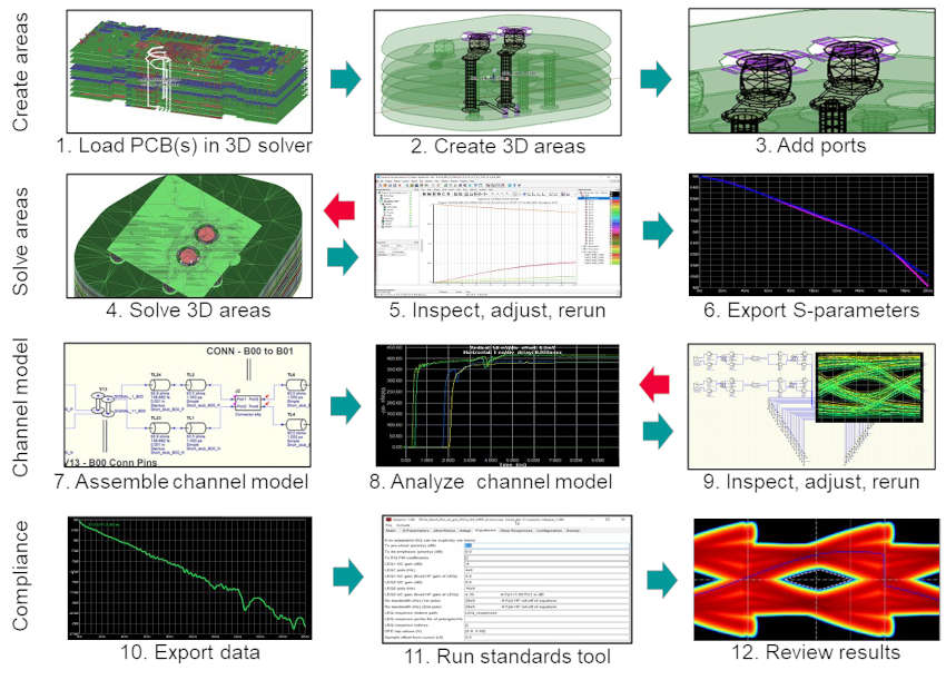
The traditional flow for post-route verification of serial channels is shown below, where red arrows indicate where data is examined, and the process is repeated for any adjustments.

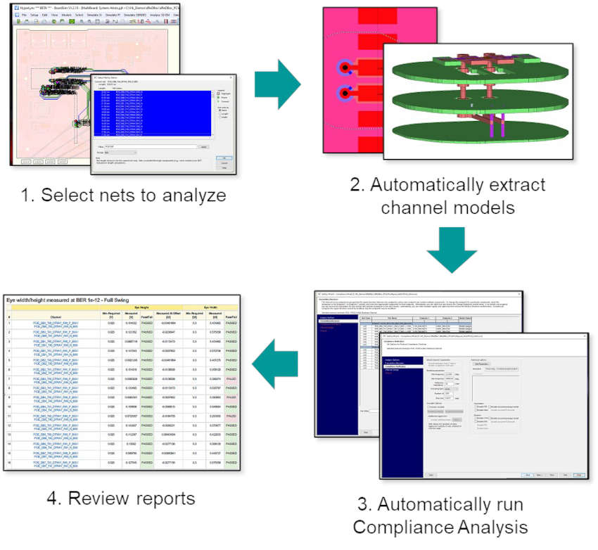
The HyperLynx flow is much simpler than the traditional compliance analysis flow, as automation helps speed up the process, so that all channels in a system design can be modeled and analyzed.

Summary
High-speed serial links require careful channel modeling, analysis and results processing to ensure reliable operation and meeting the specifications. A traditional approach has been compared to the HyperLynx approach, where the benefits of HyperLynx were noted:
- Analyze all channels in a design for compliance
- Overnight results
- Reports which channels pass or fail, and by how much margin
Read the entire 13 page white paper from Siemens online.
Related Blogs
- Siemens Promotes Digital Threads for Electronic Systems Design
- Using PCB Automation for an AI and Machine Vision Product
- DDR5 Design Approach with Clocked Receivers
- Cracking post-route Compliance Checking for High-Speed Serial Links with HyperLynx
- EDA in the Cloud with Siemens EDA at #59DAC


Comments
One Reply to “Will my High-Speed Serial Link Work?”
You must register or log in to view/post comments.