I have talked about Virtual Prototyping a SoC including FlexNoC Network on Chip IP from Arteris by using Carbon Design Systems set of tools in a previous post. A blog, posted on Carbon’ web, is clearly explaining the process to follow to optimize a fabric (FlexNoC) successively using the different tools from Carbon. Bill Neifert, CTO with Carbon Design Systems introduces the SoC context: “Fabric optimization is a prime area for architectural analysis. SoCDesigner Plus is an ideal tool for this and since it’s the only virtual prototype tool which will deliver 100% accurate results it’s extremely valuable for making crucial design decisions. It also made a lot of sense as well that Arteris IP would be requested. Their constant stream of press releases with customer design wins is pretty strong evidence of how widely their IP has been adopted.”

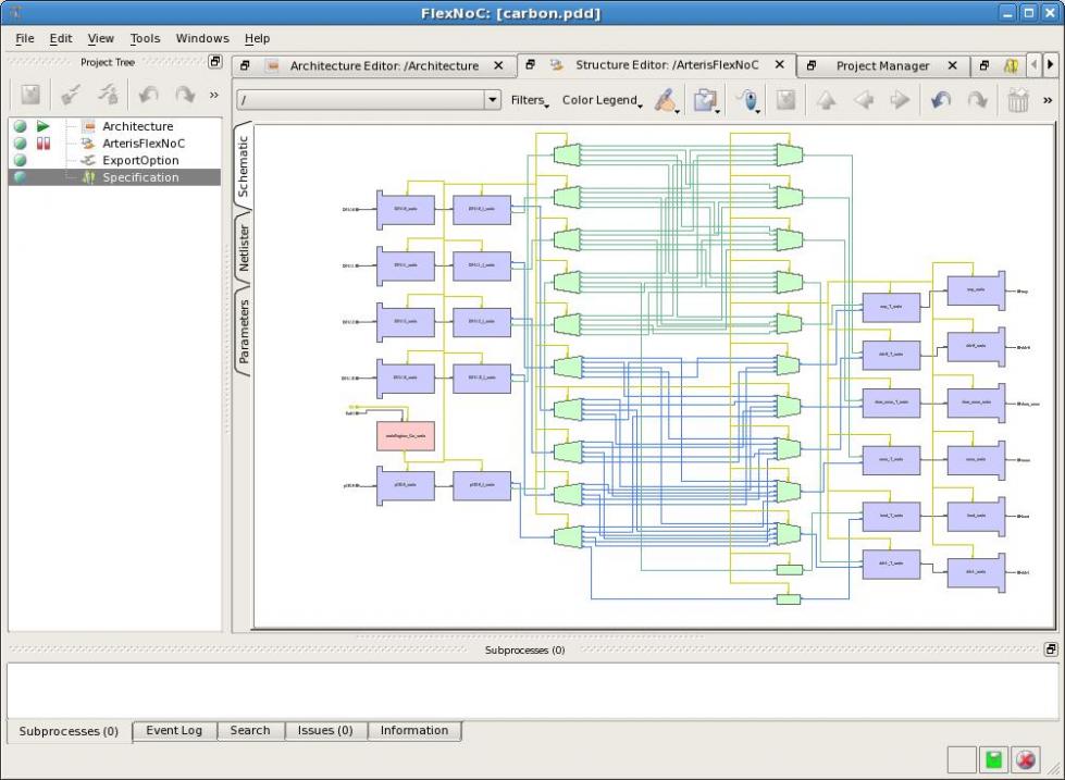
The first step is to create a 100% cycle accurate models of Arteris FlexNoC interconnect models by using Carbon Model Studio. To do so, Eric Sondhi from Carbon has used the FlexNoC project file (.PDD file) that matched AXI interconnect configuration and initial memory map definition of the system, this project file being generated either by Arteris, or by the designer using Arteris’ tools. Then, entering the project file into the FlexNoC tool to generate the Verilog RTL for the specific FlexNoC, lead to the 100% cycle accurate description. As Eric Sondhi point it out, the value that 100% cycle accurate models provide by enabling SoC developers to guarantee their functional behavior and performance results will match final silicon is huge!

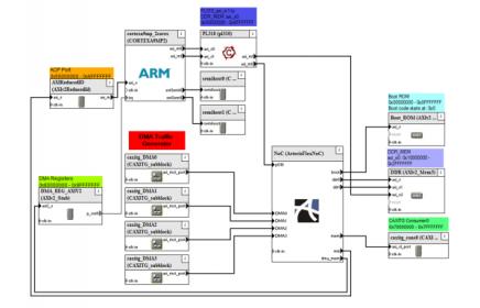
Screenshot of the Arteris FlexNoC CPAK
At this stage, the SoC designer can start virtual prototype the design, providing he has already created (or re-use) the various models describing the different functions, also generated by Carbon Model Studio. Virtual prototyping is done by assembling the different models together, with SoCDesigner Plus tool from Carbon. Once this task has been completed (there is a very accurate description of this process in Eric’s blog), the designer can start “to have fun”, and move to the Carbon Performance Analysis Kits (CPAK) tools.

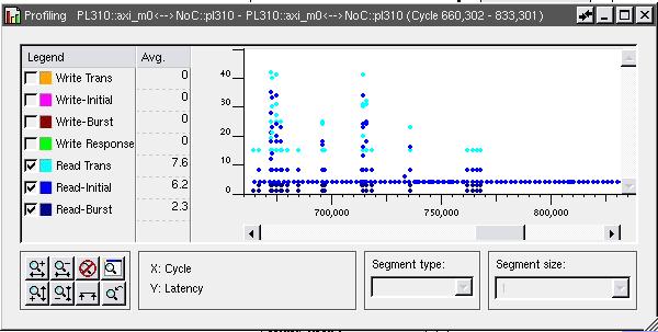
A9 Read Latencies from FlexNoC Input
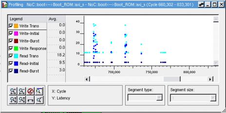
This last step is precisely described by Eric on a real-world ARM Cortex A9 based system with DMA-like traffic generators running Carbon’s ARM boot & initialization code with Performance Validation software provided in some of other CPAKS from carbon. For SoC architect, this should be the most amazing task, where he runs SoC performance analysis simulations and observe latency on both sides of the FlexNoc, then try various options in order to optimize architecture.

Read Latencies from FlexNoC Output
At this stage, you should go and read Eric’s blog to more precisely all the possibilities offered by the joint Carbon/Arteris solution, as it offers design teams a way to easily create and import accurate Arteris FlexNoC interconnect models for Carbon SoCDesigner Plus: the new Carbon/Arteris flow allows Carbon’s SoCDesigner Plus users to use Arteris FlexNoC to configure their NoC interconnect fabric IP and then upload the configuration to Carbon IP Exchange. The web portal then creates a 100% accurate virtual model of the configuration and makes it available for download and use in SoCDesigner Plus. “We see strong demand for models of Arteris’ NoC interconnect IP,” states Bill Neifert, chief technology officer at Carbon Design Systems®, the leading supplier of virtual platform and secure model solutions. “Our partnership with Arteris enables engineers to make architectural decisions and design tradeoffs based upon a 100%-accurate virtual representation.”
By Eric Esteve from IPNEST


Comments
There are no comments yet.
You must register or log in to view/post comments.