






Overview
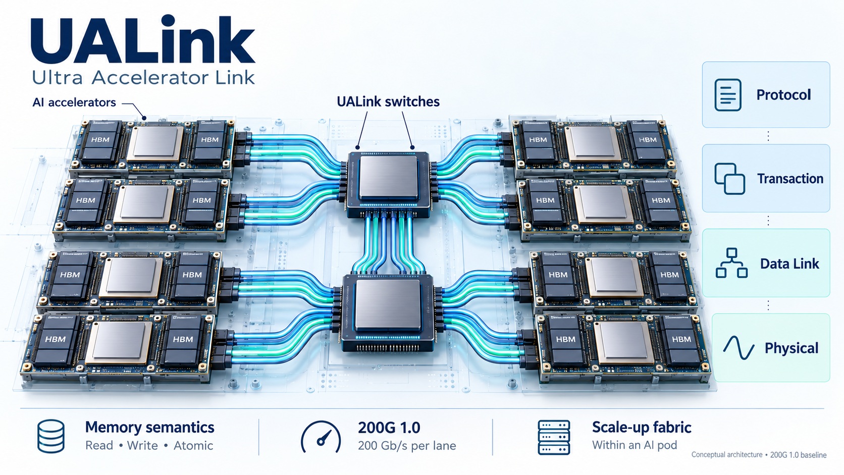
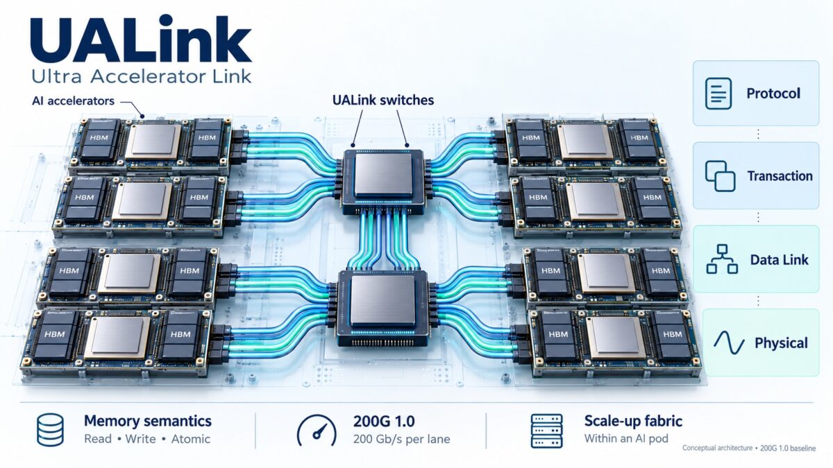
UALink is a consortium-defined scale-up interconnect for AI accelerators. Its memory-oriented fabric connects accelerators through switches inside a computing pod. The 200G 1.0 baseline specifies 200 Gb/s per lane and addressing for as many as 1,024 accelerators. [1]
Scale-up fabrics support closely coupled computation; scale-out networks connect larger distributed systems. In a practical AI deployment, both can be present. Fast communication matters when each computation step depends on data held by another accelerator.
Scope: this article explains the publicly documented 200G 1.0 architecture and summarizes the newer specification family. It is an engineering overview, not a normative implementation specification. Full evaluation specifications were not downloaded through the registration and agreement forms.
Specification family
The consortium currently lists these documents. A product’s advertised “UALink support” should identify its exact revisions. [1]
| Document | Role |
|---|---|
| 200G 1.0 | Original 200G scale-up specification |
| Common 2.0 | Adds in-network compute |
| 200G Data Link and Physical Layers 2.0 | Separates speed-dependent layers from the common specification |
| 128G Data Link and Physical Layers 1.0 | Separately listed link/PHY specification; the catalog provides no detailed description |
| Chiplet 1.01 | Chiplet integration, interfaces, flow control, management; described as compliant with UCIe 3.0 |
| Manageability 1.0 | Centralized control and management using gNMI, YANG, SAI, and Redfish |
Common 2.0’s in-network compute can move some computation into the communication fabric. The catalog describes lower communication cost and better scaling; it does not establish the supported operations, precision, or measured gains for a particular implementation. [1]
Architecture and protocol
The 1.0 overview describes software-managed coherence, read/write/atomic operations, a vendor-defined 57-bit physical address space, and source/destination routing. A station groups four lanes for up to 800 Gb/s. Hosts attach locally through interfaces such as PCIe or CXL. [2]
| Layer | Function in the 1.0 overview |
|---|---|
| Protocol interface, UPLI | Memory requests and responses; tags distinguish outstanding operations |
| Transaction layer | Credit management and FLIT packing/unpacking |
| Data link layer | Transfers between transaction and physical layers |
| Physical layer | PCS and an Ethernet-derived PHY based on IEEE P802.3dj |
Reusing Ethernet physical technology does not imply Ethernet packet compatibility. UALink endpoints and switches must implement the UALink protocol stack. [2]
Memory access model
The overview uses a partitioned global address space: software imports/exports memory, and accelerator/link MMUs translate addresses and handles. Request addresses are ordered from source to destination; completions can arrive out of order. [2]
An illustrative remote read proceeds as follows:
- Software makes a remote memory region available to the originator.
- The originator translates the address and emits a tagged read request.
- The fabric delivers it to the destination accelerator.
- The destination accesses its memory and returns the response.
- The originator matches the response to the outstanding operation.
This sequence is explanatory, not an encoding or complete ordering rule. Software-managed coherence means a developer must establish visibility and synchronization through the implementation’s runtime. Shared addressability alone does not prove CPU-style cache coherence or sequential consistency.
Bandwidth and latency
The consortium’s 2025 Q&A confirms request sizes of 64, 128, 192, or 256 bytes and station configurations of one 800G port, two 400G ports, or four 200G ports. [3]
Using nominal lane rates and decimal units:
| Configuration | Nominal rate per direction | Byte-rate equivalent |
|---|---|---|
| One 200G lane | 200 Gb/s | 25 GB/s |
| Four 200G lanes | 800 Gb/s | 100 GB/s |
| Four-lane full duplex, summed | 1,600 Gb/s across both directions | 200 GB/s aggregate |
These are arithmetic conversions, not measured application throughput. Summing transmit and receive capacity does not double the speed of a one-way transfer. Useful throughput depends on overhead, message mix, memory bandwidth, congestion, and software efficiency.
For an illustrative payload of S bytes and effective bandwidth B bytes/s:
transfer time ≈ startup latency + S / B
This engineering approximation omits contention and overlap. Small transfers emphasize startup latency; large transfers emphasize sustained bandwidth.
The Q&A gives implementation-dependent port-to-port switch latency estimates at 400G: at most 150 ns for a 25T switch, below 200 ns for 50T, and below 250 ns for 100T. These are not end-to-end application measurements. It also states that the specification does not set maximum latency and minimum bandwidth for each interface. [3]
Topology and workload implications
The endpoint-count limit does not establish the performance of every possible topology. When assessing a system, inspect switch radix, fabric stages, accelerator port count, link allocation, oversubscription, and traffic placement.
The following are engineering implications rather than UALink performance claims:
| Workload | Communication pressure | Useful measurements |
|---|---|---|
| Tensor parallelism | Frequent exchange among shards | Small-message latency; step time |
| Data parallelism | Gradient collective communication | All-reduce throughput; exposed communication |
| Mixture of experts | Token dispatch and return traffic | All-to-all performance; skew and congestion |
| Pipeline parallelism | Activation movement across stages | Transfer time; pipeline utilization |
Collective libraries determine how application operations map onto the fabric. A wire protocol by itself does not establish framework integration, collective quality, or portability across vendors.
Comparison with NVLink
Both target accelerator scale-up communication. UALink defines a consortium specification; NVLink is NVIDIA’s interconnect technology. NVIDIA also offers NVLink Fusion for integration with semi-custom ASICs or CPUs. [1][4]
| Dimension | UALink | NVLink |
|---|---|---|
| Comparison unit | Specify revision, lane/port count, and complete system | Specify generation and GPU/platform |
| Bandwidth example | 200G 1.0: four lanes yield nominal 100 GB/s per direction | NVIDIA lists 900, 1,800, and 3,000 GB/s per GPU for generations 4, 5, and 6 |
| Fabric compute | Common 2.0 introduces in-network compute | NVLink Switch includes SHARP reduction and multicast engines |
| Integration evidence | Requires product-specific hardware, runtime, and interoperability information | Requires platform-specific hardware and software information |
NVIDIA describes its sixth-generation 3 TB/s figure as bidirectional and labels the specifications preliminary. A UALink station and an NVLink GPU total use different aggregation boundaries; their numbers alone cannot establish a performance ratio. [4]
System evaluation checklist
Before making an implementation decision, obtain product-specific evidence for:
- Compatibility: exact common/link/PHY revisions and tested endpoint/switch combinations.
- Topology: bandwidth per accelerator, direction convention, switch stages, and bisection capacity.
- Memory semantics: supported atomics, synchronization, visibility, and failure behavior.
- Software: driver/runtime support and representative collective benchmarks.
- Operations: telemetry, error reporting, recovery, isolation, and fabric reconfiguration.
- Workload results: latency distributions, step time, useful throughput, and power under contention.
This checklist is engineering guidance. It does not assert that every feature is mandatory or available in every UALink implementation.
Glossary
| Term | Meaning |
|---|---|
| Pod | A group of accelerators connected by a scale-up fabric |
| FLIT | Flow-control unit used to package link traffic |
| UPLI | UALink Protocol Level Interface |
| MMU | Memory Management Unit |
| PGAS | Partitioned Global Address Space |
| Atomic operation | An indivisible update under the operation’s specified semantics |
| In-network compute | Computation performed within the communication fabric |
| Bisection bandwidth | Capacity across a cut dividing a topology into two groups |
Primary sources
- UALink specification catalog — current document family and public feature summaries.
- UALink 200G 1.0 Specification Overview — consortium-hosted technical overview by Cadence authors, May 15, 2025.
- UALink webinar Q&A — consortium responses, June 4, 2025; historical implementation estimates are identified as such above.
- NVIDIA NVLink and NVLink Switch — generation bandwidths, Fusion, and switch features.











The silent killer of analog reliability: Why SPICE misses floating net