The MOS-AK/GSA Modeling Working Group, a global compact modeling standardization forum, delivered its annual autumn compact modeling workshop on Sept. 20, 2013 as an integral part of the ESSDERC/ESSCIRC Conference in Bucharest (RO). The event received full sponsorship from leading industrial partners including Agilent Technologies, LFoundry and Microchip. More than 30 international academic researchers and modeling engineers attended two sessions to hear 12 technical compact modeling presentations and posters including the keynote by Larry Nagel.
The MOS-AK/GSA speakers discussed:
- SPICE In The Twenty-First Century (Larry Nagel, Omega Enterprises Consulting),
- NGSPICE: recent progresses and future plans (Paolo Nenzi, NGSPICE Development Team),
- KCL and Linear/NonLinear Separation in NGSPICE (Francesco Lannutti, NGSPICE Development Team),
- Modeling Junction Less FETs (Jean-Michel Sallese, EPFL),
- HiSIM-Compact Modeling Framework (Hans Juergen Mattausch, Uni. Hiroshima),
- The Correct Account of Nonzero Differential Conductance in the Saturation Regime in the MOSFET Compact Model (Valentin Turin, State University-ESPC),
- State of the Art Modeling of Passive CMOS Components (Bernd Landgraf, Infineon Technologies),
- Compact I-V Model of Amorphous Oxide TFTs (Benjamin Iniguez, URV),
- Three-Dimensional Electro-Thermal Circuit Model of Power Super-Junction MOSFET (Aleš Chvála, Uni. Bratislava),
- A Close Comparison of Silicon and Silicon Carbide Double Gate JFETs (Matthias Bucher, TUC),
- Towards wide-frequency substrate model of advanced FDSOI MOSFET (Sergej Makovejev, UCL),
- A Simple GNU Octave-Based Tool for Extraction of MOSFET Parameters (Daniel Tomaszewski, ITE).
The presentations will be open for downloads at <http://www.mos-ak.org/bucharest/>
The MOS-AK keynote speaker, Larry Nagel, delivered “SPICE in the Twenty-First Century” talk drawing a roadmap of future SPICE development directions. So how will SPICE evolve in the future? Several proprietary SPICE versions already contain one or more of these improvements, but they have not yet been migrated to open source versions.
1. SPICE will remain an Open Source tool: SPICE has lasted as long as it has in part because it is an open source tool, versions of which are available free of charge to all takers. An open source SPICE is a far better educational tool because the student can always take the tool apart to see how it works and how it can be improved. An open source SPICE a far better research tool because it can be modified to fit the needs of a new technology, even if it is not profitable for and EDA vendor to make the modification. For SPICE to continue to be successful, it must continue to be an open source tool.
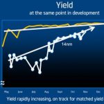
2. SPICE will take advantage of new hardware (Multicores, GPU’s, Cloud Computing, even Smart Phones): One new development in parallel circuit simulation is the XYCE “SPICE Compatible” circuit simulator that was developed at Sandia National Laboratories with the express goal of exploiting parallel processing hardware. XYCE has been in development for fourteen years and soon will be released as an Open Source tool in the very near future. Keep an eye on the website http://xyce.sandia.gov for more news.
3. SPICE will include an advanced version of ADMS to accommodate model development: It is pretty clear that the replacement for CMOS has not yet been invented. Hundreds of “new” device models will have to be added to SPICE to try out new technology ideas in the quest for a new technology. The ADMS program, originally developed by Laurent Lemaitre at Motorola, is an open source tool that was designed to compile SPICE models coded in a subset of Verilog-A into the C language routines required by most versions of SPICE. However, some newer device models, such as BSIMCMG and BSIM6, have been coded in a subset of Verilog-A that is not compatible with ADMS, so these models are not available to open source versions of SPICE. This problem has to be fixed.
4. SPICE will accept Verilog-A as input: In addition to being able to accept device models coded in Verilog-A, it would be highly desirable to have SPICE accept netlists that are compatible with Verilog-A. This compatibility will aid compact model development by allowing the full power of Verliog-A language. Verilog-A compatibility also will allow noncritical portions of the circuit to be described at the behavioral level. Partitioning the circuit into behavioral (functional) blocks will aid parallelization.
5. SPICE will include RF Analysis: By the end of the 1980’s, at around the 1µm technology node, CMOS transistor fT had extended well into the GHz region. As transistors became faster, it became possible to integrate RF circuits and the wireless explosion began. This necessitated an entirely new line of algorithms and simulators. Each simulator had different algorithms that worked on some RF circuits but not others. The user interface and netlist description varied from program to program. With the exception of Qucs, none of the programs were Open Source. Because of the lack of open source RF simulation tools, RF simulators are only slowly working their way into educational institutions.
6. SPICE will include Variational Analysis: Variational analysis in the past has been added to SPICE almost as an afterthought. As an educational tool, students now need to learn variational analysis from the very start. Variational analysis no longer can be treated as an afterthought! New technologies now have to be specified with random variations, and SPICE needs to have Variational Analysis integrated into its basic framework.
7. SPICE will include Thermal Analysis: Devices are being placed closer and closer to each other, and devices are being placed on substrates that are not good thermal conductors. MOSFET models already include thermal effects, but only self heating is included. Thermal coupling between devices is or will be significant in analog IC design, and Larry Nagel thinks this analysis feature will become more important as time goes on.
This list is hardly all inclusive. After forty years of development, there still are dozens of new features and enhancements that are needed by analog circuit designers! Larry Nagel’s list represents those features that he think are most pressing, but of course every analog designer will have his or her own list which may or may not include these seven items. The future of SPICE is indeed bright, even after all these years.
The MOS-AK/GSA Modeling Working Group is coordinating several upcoming modeling events to focus on the Verilog-A compact model standardization as well as open source SPICE developments: a winter Q4/2013 MOS-AK/GSA meeting in Washington DC (http://www.mos-ak.org/washington_dc_2013/), and a spring Q2/2014 MOS-AK/GSA meeting in London (http://www.mos-ak.org); a special compact modeling session at the MIXDES’14 Conference in Lwow (https://www.mixdes.org); an autumn Q3/2014 MOS-AK/GSA workshop in Venice.
In the meantime please also visit <http://www.mos-ak.org/washington_dc_2013/> where we will continue the discussion of all compact/SPICE modeling topics.
lang: en_US