At the end of last month during ISSCC there was a forum organized by the SOI Consortium. It took place in San Francisco at the Palace Hotel (which, if you have never been there, is famous for converting its old entryway for carriages into an amazing dining room, and for a bar with a huge painting by Maxfield Parrish of the Pied Piper valued at over $5M, up a little from its original price of $6K). There were presentations on:
- FD-SOI advantages for applications and ecosystem, Philippe Magarshack, STMicroelectronics
- 28FD-SOI: Cost effective low power solution for long lived 28nm by Kelvin Low, Samsung
- Synopsys FD-SOI IP Solutions, Mike McAweeney, Synopsys
- FD-SOI: Ecosystem and IP Design, Amir Bar-Niv, Cadence
- FD-SOI Promises for 100Gb/s and Beyond Optical Transceiver, Naim Ben-Hamida, Ciena
- 28nm FD-SOI Design/IP Infrastructure, by Shirley Jin, Verisilicon
- Driving Profitable Innovation and Rapidly Growing Ecosystems with a Semiconductor Start-up Incubator,Mike Noonen, Silicon Catalyst
- RFSOI: Redefining mobility and more in the front-end, Mark Ireland, IBM
- Towards a Highly-Integrated Front-End Module in RF-SOI using Electrical-Balance Duplexers, Barend Van Liempd, imec
- RF SOI: from Material to ICs – an Innovative Characterization Approach, Mostafa Emam, Incize
- ST H9SOI_FEM: 0.13µm RF-SOI Technology for Front End Module Integration, Laura Formenti, STMicroelectronics
- SOI: An Enabler for RF Innovation and Wireless Market Disruption, Peter Rabbeni, GlobalFoundries
There was also a panel discussion moderated by our own Dan Nenni.
See also RF on SOI at GF
When FD-SOI was first being talked about it was perceived as a purely STMicroelectronics initiative. The whole world was going FinFET except for ST. But since then there have been a regular stream of announcements as the ecosystem expanded. GlobalFoundries announced that they had licensed FD-SOI in 2013 (but have not really said anything since). Samsung announced that they had licensed FD-SOI in June last year just before DAC. In January at the Tokyo forum Sony announced a chip they had built on FD-SOI. At Embedded World Freescale (soon to be merged with NXP) announced they were designing chips in FD-SOI. And on Dan’s panel Cisco discussed their own experiences. Ciena also presented their experiences at the San Francisco forum.
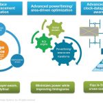
Since Samsung are a foundry, Kelvin Low’s presentation was one of the more important. If FD-SOI is going to be relevant then it needs to have availability from multiple sources. Samsung are clearly looking at 28FD-SOI as an extender for planar 28nm:
- lower power
- similar manufacturing cost (FEOL is simpler, which offsets higher substrate cost; BEOL is identical)
- cheaper cost per transistor than FinFET
- higher performance
- easy port of designs from planar
These attributes make it a great basis for internet of things (IoT) applications which do require low power but don’t need the complexity of 14/16nm FinFET.
Kelvin said that the process had passed wafer level reliability (WLR) qualification in September last year. Samsung themselves are providing the foundation libraries and basic IP support. IP vendors are providing higher level IP (much of it at the RTL level of course) and design partners are providing ASIC design services.
All the presentations from the forum are here (or will be, some are not yet received).