




To answer this question, I will share the results about Interface IP, more precisely the Top 5. The Top 5 protocols, USB, PCIe, Ethernet, DDRn and MIPI, are part of the interface IP market and each of them has been characterized by very strong growth rate. If you compute actual numbers for 2010 to 2014, it results to a Cumulated Annual Growth Rate (CAGR) of 14%.
Continue reading “Is the IP market expected to decline by 2020?”

Learning about 3D Integration of ICs and Systems
We blog a lot about Moore’s Law, and even “More than Moore” where 3D integration of ICs and systems are used to get lower product costs. One big challenge with 3D integration of ICs is that most EDA software was really intended only for abstracting at 2D or 2.5D structures. Over the past several years there have been new EDA tools developed that do specifically address the 3D nature of new IC design and packaging. If you’re interested in 3D ICs then consider attending a webinar from Silvaco on Thursday, October 22nd to get some new insight for two specific aspects: Partitioning and DRC for 3D systems and ICs.If you’re an IC engineer or manager looking for better ways to implement 3D designs and analyze, then here’s a summary of what to expect:
- Entry barrier: Difficulties facing 3D ICs and heterogeneous designers.
- EDA Concept: Rationale behind the novel 3D space partitioning software and its integration with the 3D DRC tool
- Design targets: Concept of weighted formulated design penalties
- Design conflicts: Co-optimization of multi-physics criteria
- Speed: High abstraction level for very fast simulations of complex orthogonal design criteria
- Manufacturability: How the DRC violations in 3D space can be easily visualized and corrected
- Case studies – 3D partitioning: How to obtain an optimal partitioning and placement of the blocks composing a 3D system in very short time
- Case studies – 3D DRC: how to apply DRC checks in 3D space to feed subsequent full routing and final verification using traditional functional simulators
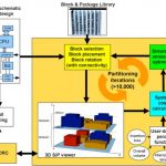
Let me start by showing you a 3D design flow prototype:In the upper-left corner is our top-level schematic of a SiP (System in Package) design. On the top is the block and package library, so the challenge is to figure out how to place and partition each block in a 3D design efficiently and that meets cost goals. Inside the gold box is where all of the partitioning iterations are performed automatically, while giving you feedback about the costs of building each 3D instance.In the lower left is the 3D DRC function, where you would find out if your selected 3D design passes all of the Design Rule Checks for manufacturing.3D DRC ViolationsThis webinar is presented by Stefano Pettazzi who earned his MS degree in EE from the University of Pavia, Italy. Stefano has been with Silvaco since 2012 and has 15 years experience with both EDA and microelectronics companies. The webinar runs from 4PM to 5PM (BST) and registration is required. If you live in a different timezone, it’s still OK to register for this webinar and then receive an email link to the archived video so that you can view it a more convenient time.Related:
Our Own Cadence Amongst the Best Multinational Workplaces!

There were some very happy faces around MemCon this week for a variety of reasons. Paul McLellan was smiling because he now works full time for Cadence and has the best medical benefits ever and of course I was smiling because there was free food!
Continue reading “Our Own Cadence Amongst the Best Multinational Workplaces!”
Wafer-Level Chip-Scale Packaging Technology Challenges and Solutions
At the recent TSMC OIP symposium, Bill Acito from Cadence and Chin-her Chien from TSMC provided an insightful presentation on their recent collaboration, to support TSMC’s Integrated FanOut (InFO) packaging solution. The chip and package implementation environments remain quite separate. The issues uncovered in bridging that gap were subtle – the approaches that Cadence described to tackle these issues are another example of the productive alliance between TSMC and their EDA partners.
WLCSP Background
Wafer-level chip-scale packaging was introduced in the late 1990’s, and has evolved to provide an extremely high-volume, low-cost solution.
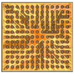
Wafer fabrication processing is used to add solder bumps to the die top surface at a pitch compatible with direct printed circuit board assembly – no additional substrate or interposer is used. A top-level thick metal redistribution layer is used to connect from pads at the die periphery to bump locations. The common terminology for this pattern is a “fan-in design”, as the RDL connections are directed internally from pads to the bump array.
[Ref: “WLCSP”, Freescale Application Note AN3846]
WLCSP surface-mount assembly is now a well-established technology – yet, the fragility of the tested-good silicon die during the subsequent dicing, (wafer-level or tape reel) pick, place, and PCB assembly steps remains a concern.
To protect the die, a backside epoxy can be applied prior to dicing. To further enhance post-assembly attach strength and reliability, an underfill resin with an appropriate coefficient of thermal expansion is injected.
A unique process can be used to provide further protection of the backside and also the four sides of the die prior to assembly – an “encapsulated” WLCSP. This process involves separating and re-placing the die on a (300mm) wafer, which will be used as a temporary carrier.
The development of this encapsulation process has also enabled a new WLCSP offering, namely a “fan-out” pad-to-bump topology.
Chip technology scaling has enabled tighter pad pitch and higher I/O counts, which necessitate a “fan-out” design style to match the less aggressively-scaled PCB pad technology. TSMC’s new InFO design enables a greater diversity of bump patterns. Indeed, it offers comparable flexibility as conventional (non-WLCSP) packaging.
Briefly, the fan-out technology starts by adding an adhesive layer to the wafer carrier. Die are (extremely accurately!) placed on this layer at a precise separation, face-down to protect the active top die surface. A molding compound is applied across the die backsides, then cured. The adhesive layer and original wafer are de-attached, resulting in a “reconstituted” wafer of fully-encapsulated die embedded in the compound:
(Source: TSMC. Molding between die highlighted in blue. WLCSP fan-out wiring to bumps extends outside the die area.)
This new structure can then be subjected to “conventional” wafer fabrication steps to complete the package:
- addition of dielectric and metal layer(s) to the die top surface
- patterning of metals and (through-molding) vias
- addition of Under Bump Metal, or UBM (optional, if the final RDL layer can be used instead)
- final dielectric and bump patterning
- dicing, with molding in place on all four sides and back
- back-grind to thin the final package
As illustrated in the figure, multi-chip and multi-layer wiring options are supported.
InFO design and verification Cadence tool flow
Cadence described the tool enhancements developed to support the InFO package. The key issue(s) arose from the “chip-like” reconstituted wafer process fabrication.
For InFO physical design, TSMC provides design rules in the familiar verification infrastructure for chip design, using a tool such as Cadence’s PVS. As an example, there are metal fill and metal density requirements associated with the fan-out metal layer(s) that are akin to existing chip design rules, a natural for PVS. (After the final package is backside-thinned, warpage is a major concern, requiring close attention to metal densities.)
Yet, InFO design is undertaken by package designers familiar with tools such as Cadence’s Allegro Package Designer or SiP Layout, not Virtuoso. As a result, the typical data representation associated with package design (Gerber 274X) needs to be replaced with GDS-II.
Continuous arcs/circles and any-angle routing need to be “vectorized” in GDS-II streamout from the packaging tools, in such a manner to be acceptable to the DRC runset – e.g., “no tiny DRC’s after vectorization”.
Viewing of PVS-generated DRC errors needs to be integrated into the package design tool environment.
Additionally, algorithms are needed to perforate wide metal into meshes. Routing algorithms for InFO were enhanced. Fan-out bump placements (“ballout”) should be optimized during co-design, both for density and to minimize the number of RDL layers required from the chip pinout.
For electrical analysis of the final design, integration of the InFO data with extraction, signal integrity, and power integrity tools (such as Cadence’s Sigrity) is required.
Cadence will be releasing an InFO design kit in partnership with TSMC, integrated with their APD and SiP products, to enable package designers to work seamlessly with (“chip design-like”) InFO WLCSP data. The bridging of these two traditionally separate domains is pretty exciting stuff.
-chipguy
A Connectivity Verification Idea
A Wirble
In case you hadn’t noticed, I like to write from time to time about EDA product ideas. I assume these are somewhat original, but given the maxim “there’s nothing new under the sun…”, I may well be wrong. In any event, I like to share these ideas if only to demonstrate that innovation in EDA is not stalled because we’ve run out big, exciting things to do. I’ll grant there are plenty of challenges on the business side but I’m hopeful that sooner or later someone will prove that profitable innovation outside the box is still possible.
We start with a proven problem: verification, the monster eating SoC design resources and schedule. High coverage, the benchmark of verification completeness as it used to be understood, has become a distant memory replaced by concepts such as “test all reasonable software use-cases” and “test until you run out of time”. Part of the problem is that the directed-random approach so effective at the IP level does not scale to SoC, leaving you with inevitably bounded case-based testing and an abiding suspicion that gremlins may still lurk in use-modes you haven’t tested.
And that motivates interest in static verification of integration-level logic as a way to get to at least one component of coverage completeness. Conventional wisdom builds a giant spreadsheet of expected connections between IPs, qualified by configuration settings and simple temporal conditions. A checker verifies that the SoC-level RTL is consistent with this spreadsheet, using graph-tracing and closely-bounded formal analysis, without needing to drill down inside IP-level logic. Because these are static checks, a complete check of all connections offers a coverage-like sense of confidence for this verification objective.
Nobody believes this is a great solution. It’s a huge amount of work and it’s massively tedious to develop the spreadsheet. And it is just as likely to be as error-prone as the RTL and probably will repeat systematic interpretation errors in the RTL, since it will be developed by the RTL design team or or a closely-related team.
So here’s the product idea. Spreadsheet approaches fall short because they are too atomic. They are a kind of machine-code representation of the integration when what we want is a higher-level, human-readable view: under such-and-such configuration settings, this IP gets a clock of this frequency or this reset pin gets a warm reset from this reset generator pin with a stall of 10 cycles before being released or … So I propose a tool that could first reverse-engineer this architectural intent from the implemented RTL. I call it a “What I Really Built Logic Extractor” or Wirble (the name is at least memorable and I’m no longer responsible for real product names).
A Wirble abstracts architecture one plane at a time: clock, reset, interrupt, bus, test, IO, .., just at the integration level, not down into IP. It may need a few hints here and there (for example this is a PLL clock output pin) but whatever may be required will be orders of magnitude simpler than what is a required for a spreadsheet. It then builds, per plane, a table or graph, a timing diagram or a very abstracted logic description showing what resources are delivered from what sources, under what conditions, to what consumers. This might be a static representation or a dynamic view where you can click through configuration options. For clocks you have to understand multipliers and dividers and muxes and gating, for resets you want to understand reset domains and what activates them (at a high level) and with what stalls. And so on.
All of this should (if well implemented) be much easier for a designer or architect to scan and immediately spot implementation problems – wherever what you really built doesn’t match what you should have built. Perhaps you may even conclude there was a bug in the spec, leading you to a corrected or perhaps even improved implementation.
I’m not claiming this will be easy. This is a tough (but I think tractable) problem with high potential value. It will require graph-tracing and formal (with cleverness in black-boxing, so formal doesn’t get lost). It will require a lot of special-case handling to cover different architectures (this is nothing new – synthesis has mass amounts of special-casing to handle different RTL structures). And it will require a clever and very intuitive representation of abstracted functionality which a designer can scan quickly for potential errors. On the plus side, it isn’t necessary to handle every plane from the outset. A Wirble that could do a good job on the clock and reset planes would provide immediate value in verification; support for more planes could be added over time.
Once the SoC team has a signed off Wirble output, they now have a human-readable regression standard against which subsequent Wirble runs could compare as the design progresses, and report not simply that connection XYZ is different from the latest RTL drop, but also that the USB external clock is disabled in configuration ABC where before it was enabled.
One last thought. Perhaps instead of abstracting Wirble output from an SoC RTL, you could do a reverse-Wirble and generate that plane of integration logic from a hand-created Wirble spec. That means you now have an integration which is correct by construction. And you can still Wirble-verify that what was generated was what you expected. Lest you think I am now completely in fantasy-land, I know of at least one design company that is already doing something very similar.
That’s it – build a Wirble if you want to build something out of the ordinary. But please don’t ask me detailed market or implementation questions. I gave you the concept, the rest is up to you.
EUV sees further delays?
Headwinds which will likely continue into 2016…
ASML reported revenues of 1.55B Euros with EPS of 0.75 Euros more or less in line with expectations. Orders were the weak spot, falling to 904M Euros versus the previous Q2 orders of 1.523B Euros. The company guided Q4 revenues to be down about 10% to 1.4B Euros below current flattish expectations. The company largely blamed foundry weakness as the primary culprit but we are concerned that they will also see memory slowing much as other equipment companies have reported.
EUV stumbles & delays yet again…..Intel likely part of the pushout
The company now expects to ship only 4 EUV systems in 2015 versus the prior expectation of 7 systems. We had predicted this push out yesterday after hearing Intel’s comments on their call which all but named ASML as the equipment company.
The key issue here is why?
ASML said that customers were being cautious and that was the reason for the delay. However, Intel said that the tool(s) needed to be reconfigured for higher output (ie; they either weren’t making spec or didn’t make required milestones).
Intels CEO, BK said “So you have to remember, there is this lag, and that’s why, as we looked at the tool, actually, we are making an adjustment on the efficiency of that tool, basically the number of units per tool out. In order to get more capacity, when that tool is really required”
It sounds like he is saying that the units per tool (read that as wafer throughput) is too low and needs to be higher. Interestingly he also added that when the tool is really required which would indicate its not yet required so we can push it out and wait for the latest and greatest version of the tool when its ready for prime time….sounds a lot like it may not be required for 10nm (as Intel has stated they have a non EUV process flow for 10nm). This is not the first time that Intel has laid the blame on ASML as we have previously pointed out.
Immersion tools slipping?
We would point out that the number of immersion tools shipping is slipping over the last year. While upgrades and service increase may point to customers finding other ways to get more out of existing tools it could be that customers don’t want to invest more in new, expensive immersion tools while waiting for next generation EUV. Its likely we are seeing more equipment reuse in the near term.
EUV system up time still an issue…
ASML said that at “certain select customers” EUV had up time of 70%. which sounds a lot like if you averaged the whole customer base that up times would likely be well below 50%. So even if you can do 1000 wafers per day, the up time cuts that in half to 500 wafers per day (or less) suggesting we still have a long way to go in improvements
Memory risk…
So far, ASML has not seen as much of a drop off in memory spend as others in the industry have reported . Memory went from 38% of orders to 52% of orders in the current quarter. Given concerns about memory pricing and the overall stability of the memory market we think this high exposure adds risk. Orders also fell from 41 systems in Q2 to 32 systems in Q3 with foundry falling from 38% to 23% and IDM (likely Intel) fell sharply from 39% of orders to 10%.
The stock…
As expected the stock had a negative reaction. We think there may be more downside as investors digest the EUV issues and memory risks. The company did not say a lot about 2016 which makes us a bit nervous about the outlook for next year if memory does indeed slow. We think there could be potential downside to $80ish.
Robert Maire
Semiconductor Advisors LLC
Why ARM Enabling Easy Access to Customized SOC’s Matters
The introduction of the Arduino heralded the huge growth and interest in MCU based designs by people who could never before easily put together the hardware and software system required for implementation of their ideas. I remember the first time I saw the Arduino in use. I was at a talk on how a system for controlling propane jet solenoids for an art project had been put together in a matter of a few days on site at an art installation. Seeing how easily the presenter was able to connect the devices to a user interface and write the firmware got my immediate attention. This was around 2008.
The Arduino project has grown from a few open source developers into major initiatives at companies like ARM, Freescale, ST, Atmel and many others. Arduinos have moved from the Atmel AVR based processors to ARM based processors, very often using the Cortex-M0. Other open platforms have evolved too, for instance the ARM mbed initiative. What all this has done is enable a huge wave of innovation, allowing people to get their ideas implemented quickly and at low cost, lowering the barriers to product development.
Unfortunately, up until now, people who wanted to go to the next level and get their products into custom SOC’s were out of luck. Companies whose products are implemented on PCB’s with SMD’s for each separate component could benefit hugely from the advantages of a custom SOC. Their products would be much smaller and could fit into wearable size enclosures. Power consumption would be reduced, reliability would go up, and assembly and PCB costs would go down. The alternative today is to buy standard parts and solder them up, but often compromises are made with off the shelf parts in terms of functionality and form factor.
ARM has just announced a revolutionary new initiative to bring custom SOC’s within reach of system and product designers that would have never been able to take advantage of their benefits. ARM is making its popular low power 32-bit Cortex M0 available for download, along with the design kit and three months of free access to the ARM Keil MDK development tool. With this comes system IP, peripherals, test bench and software. There is even an option to buy a FPGA board for under $1,000 to aid in prototyping.
Once it’s time to move to the next stage of product development, a license to manufacture products containing the Cortex-M0 can be purchased with an easy to buy $40,000 IP license from ARM. The Cortex-M0 is a very popular processor for IoT, mobile and wearable applications. It is extremely low power yet offers 32-bit computing power.
Despite this radically different technology access and licensing model if there is still concern about how to actually implement an SOC, ARM is further enabling SOC development by linking its Design House partners with product developers. Partners like Brite, Dream Chip, S3 Group, Open-Silicon and others, offer turnkey development as well as consultancy or help for custom SOC development. There is also cooperation with a large number of foundries, such as licensing models that include ARM IP costs as a minimal add-on in the foundry fabrication cost.
This is a game changer for people who have product ideas but cannot effectively implement them without a custom SOC. We saw a proliferation of design ideas and collateral technology spin offs from the Arduino. One notable example are 3D printers, most of which have a controller board descended from the Arduino. In the same vein this initiative from ARM will continue the democratization of technology that the maker movement started. Only now, even more complex and traditionally more difficult design options will be available to a larger audience.
Optimizing Quality-of-Service in a Network-on-Chip Architecture
The Linley Group is well-known for their esteemed Microprocessor Report publication, now in its 28th year. Accompanying their repertoire of industry reports, TLG also sponsors regular conferences, highlighting the latest developments in processor architecture and implementation.
One of the highlights of the conference was the presentation from Benoit de Lescure, Director of Application Engineering at Arteris, and Marc Greenberg, Director of Product Marketing at Synopsys. Benoit provided an update on Network-on-Chip (NoC) architecture design, with an emphasis on optimizing transactions to the unique capabilities of LPDDR4 memory. Marc joined Benoit, to describe how the Synopsys memory controller IP integrates with the new Arteris NoC memory transaction scheduling unit for LPDDR4.
NoC Basics
As SoC designs integrate a greater number and diversity of processing units, traditional crossbar or hierarchical (multi-level) bus architectures do not scale. Routing congestion becomes a major issue for physical implementation, while satisfying Quality-of-Service (QoS) requirements becomes a difficult timing closure task.
Most users associate the term Quality-of-Service with the allocation and scheduling of resources to provide computation that meets critical deadline constraints, typically under the supervision of a real-time operating system. In the context of an SoC with many disparate processing blocks, similar QoS considerations apply. The very heterogeneous types of data traffic on a processor SoC will have different latency and bandwidth requirements:
- protocol
- clock frequency
- data width
- peak throughput
- traffic patterns – e.g., transaction length, address alignment
- reaction to latency and/or “back pressure” from pending requests
These system performance characteristics require specific focus on:
- throughput of multiple concurrent links (bandwidth)
- delay from a request initiated by a master through the interconnect to the target (latency)
- memory efficiency (% of maximum memory throughput realized, sharing the finite memory bandwidth across many command requests)
In essence, a Network-on-Chip implementation involves encapsulating data traffic between processing units into packets, and transporting those packets serially, in a pipelined manner. This enables scaling of SoC complexity, while managing physical routing congestion and satisfying QoS requirements.
As Marc put it, “The goal of the NoC and memory controller is to get the right data to the right master at the right time.”
QoS in a NoC Architecture
The Arteris NoC architecture consists of Network Interface Units (NIU), which communicate directly with each IP core. This logic converts traditional (AMBA AXI, AHB, OCP, or customer proprietary) protocol transactions into packets for transport across the NoC network fabric. At the receiving end, the NIU communicates with a core using an IP socket interface.
The Arteris FlexNoC solution provides synthesizable RTL modules for physical implementation of the NoC. The NIU logic is typically places close to the related IP core in the chip floorplan, to optimize timing and minimize routing congestion. Pipeline register insertion is supported, to optimize timing. And, to be sure, the FlexNoC package includes a suite of SystemC TLM simulation and performance analysis tools.
The NoC fabric specifically addresses QoS bandwidth and latency requirements in several ways:
- packet priority assignment (by packet, or by all socket transactions)
- dynamic “pressure” relief (provide a low latency path to high-priority packets when traffic is high)
- communication between cascaded arbiters at each network switch (to avoid deadlocks)
and the main emphasis of Benoit’s and Marc’s presentation:
- optimization of the memory scheduler DDR commands to the memory controller IP block, for highest memory efficiency and fewest wait states
NoC QoS with LPDDR4
The advent of LPDDR4 introduces new features in physical memory addressing and timing – with these new features comes opportunities for additional QoS optimizations. Benoit and Marc described how Arteris and Synopsys have collaborated to leverage these new capabilities.
The NoC memory request scheduler and memory controller optimize the sequence of LPDDR4 commands to the shared memory, managing:
- multiple, independent LPDDR4 channels
- memory interleaving (logical-to-physical mapping), to optimize addresses for low “locality of reference” packets
- coherent (and non-coherent) memory requirements for different IP cores
- power dissipation options, separating critical functions from active/standby memory areas
- per bank refresh scheduling
- PHY training/calibration cycles
As SoC processors continue to integrate a greater number and complexity of IP cores, the scalability of the NoC architecture provides a key advantage. The QoS performance requirements of the various core functions will result in a wide set of characteristic “traffic” through the network switch fabric, with varying bandwidth and latency requirements. Specifically, the schedule of memory commands needs to be optimized to achieve QoS metrics, taking maximum opportunity to leverage new LPDDR4 features.
Arteris and Synopsys recently illustrated how a collaborative development partnership between NoC architecture and memory controller IP provider can achieve significantly improved power/performance.
For a great summary of the recent TLG Processor Conference, check out Tom Simon’s recent article:
http://www.semiwiki.com/forum/content/5086-processors-rule-day.html
-chipguy
Convolutional Deep Neural Network is now a reality with CEVA-XM4
XM4 DSP has been enriched with CEVA Deep Neural Network (CDNN) Software Framework. Some explanation could be useful before jumping into CDNN. The “Deep” of CDNN comes from “Deep Learning”, a family of neural network methods using high number of layers, so a deep network. The most popular deep learning neural network method is the “Convolutional Neural Network”. Why is it popular? Because CNN focus on feature representations, required to support applications like object recognition, driver assistance (ADAS) or augmented reality, to name a few emerging applications becoming very popular, generating developments in various segments, from automotive to consumer. CNN offer two major benefits, justifying this infatuation. At first, CNN provides best recognition quality when compared with alternative recognition algorithms. The second benefit is linked with the artificial intelligence nature of the algorithm: the designer will implement it once and be able to use it many times without code change, through re-training. Such a benefit could greatly accelerate machine learning deployment for embedded systems, as, by definition, you want such systems to run as long as possible without intervention.
CEVA has run a partnership with Phi Algorithm Solutions and optimized the CNN-based Universal Object Detection (UOD) algorithm from Phi, and ported it to CEVA-XM4 via CDNN. The first “N” of CNN is for Neural, indicating that researchers strive to mimic the human brain in computers. Such work was limited mainly by computing horsepower, power constraints and algorithmic quality, but the technology progresses allow to bring neural network in the embedded world. Harnessing the computing power of the CEVA-XM4 imaging & vision DSP, the partners have created the lowest power and memory bandwidth deep learning solution providing real-time, efficient object recognition and vision analytics.
The concept of pre-trained networks is brilliant: the designer receives network model & weights as design inputs from offline training (pre-trained) and these are automatically converted into a real-time network model, via CEVA Network generator. He can utilize this real-time network model in CNN application on CEVA XM4 DSP. This usage flow is described below (Caffe is a popular open source software framework, used to build, train, activate neural networks).
If you look at the usage flow, CEVA main contribution is the Network Generator, allowing merging two distinct know-how. The 100% software based science using floating-point algorithms on the left side has to be converted into fixed point, power aware and hardware compatible customized network to be implemented into an embedded DSP… keeping high recognition accuracy. CEVA claims less than 1% degradation in accuracy compared to the original network, which means that in less than 1% of cases, the pictured Labrador retriever could be confused with a Beagle.
CNN-based Universal Object Detector algorithm (from Phi Algorithm Solution) is now available for application developers and OEMs to run a variety of applications including pedestrian detection and face detection for security, ADAS and other embedded devices based around low-power camera-enabled systems.
Taking the example of pedestrian detection the real-time detection application utilizing CDNN and optimized for CEVA-XM4 DSP exhibit less than 30 mW for 1080p, 30 fps and provide 15x average memory bandwidth reduction compared to typical neural network implementations. This makes it the lowest power deep learning solution for embedded systems: 30x lower power and 3x faster processing when compared to leading GPU-based systems.
According with Eran Briman, vice president of marketing at CEVA, “Our new Deep Neural Network framework for the CEVA-XM4 is the first of its kind in the embedded industry, providing a significant step forward for developers looking to implement viable deep learning algorithms within power-constrained embedded systems.” The CEVA-XM4 imaging & vision DSP together with the CDNN framework paves the way to advances in artificial intelligence devices in the coming years using deep learning techniques.
By Eric Esteve from IPNEST
Wi-Fi Pioneers: Where are they now?
Wi-Fi is the unsung hero of the mobile revolution. Some people even call it the real Internet. In retrospect, smartphones took off partly because Apple forced mobile operators to seriously consider handsets with Wi-Fi capabilities. Now Wi-Fi is an intrinsic networking component serving smartphones, tablets and notebook computers in home, office and public environments.
The origins of Wi-Fi can be traced back to the 1980s when the wired networks like Ethernet were just taking off. The article briefly chronicles the work of three pioneers who laid the groundwork for one of the most successful facets of the Internet.
Michael Marcus:
The man who proposed the idea of ISM band
In 1980, an engineer named Michael Marcus proposed the idea of opening up the 900 MHz industrial, science and medical (ISM) band at 2.4 GHz and 5.8 GHz frequencies. Marcus theorized that license-free radio spectrum in the hands of technology entrepreneurs would stimulate innovation and thus yield productive benefits.
After five years of prodding from Marcus, in 1985, the Federal Communications Commission (FCC) opened up the so-called garbage band allocated for household devices like microwave ovens and radio-controlled toy cars. However, the commission mandated that this new license-free band would use spread spectrum technology to ensure that there was no interference with the existing devices using the ISM band.
Where is he now?
Marcus now heads a consultancy firm Marcus Spectrum Solutions LLC that is located in Washington D.C. area and provides wireless spectrum-related services like certifications and training.
Victor Hayes:
Hayes led the IEEE 802.11 committee through its first decade
In the 1980s, IT equipment maker NCR Corp. faced a problem: its retail customers changed their floor plan from time to time, and when they did that, the NCR-provided cash registers had to move and be re-connected to the computer servers. So in 1988, NCR, which wanted to use the unlicensed radio spectrum to hook up its wireless cash registers, asked protocols specialist Victor Hayes to look into this technology prospect.
The engineering teams of NCR and its joint venture partner AT&T eventually developed the Wi-Fi technology in 1991 in Neuwegein, the Netherlands. The product called WaveLAN—offering speeds of 1 Mbit/s to 2 Mbit/s—would serve cashier systems in a wireless environment.
Hayes was the first chair of the IEEE 802.11 group, which in 1997 finalized the wireless standard that later became known to the world as Wi-Fi. The Netherlands native, who had joined NCR in 1974, is often being referred to as the “Father of Wi-Fi” for his role in establishing and chairing the IEEE 802.11 Standards Working Group for Wireless LANs.
Where is he now?
Hayes is now senior research fellow at the Delft University of Technology, the Netherlands, where he carries out development work for flexible wireless spectrum management.
Bruce Tuch:
Tuch was a lead innovator in the Wi-Fi development arena
Bruce Tuch was working as an RF engineer at Bell Labs when he got involved in work related to WaveLAN, of product of NCR, which had now been acquired by Bell Labs’ parent company AT&T. Subsequently, Hayes and Tuch approached the Institute of Electrical and Electronics Engineers (IEEE), where a committee named 802.3 had earlier developed the Ethernet LAN standard. Consequently, a new committee called 802.11 was formed, and work on a new wireless LAN standard began.
After his early contribution in the development of WaveLAN product and technology standardization at IEEE 802.11 committee, he continued to lead the Wi-Fi development efforts at the Agere System’s Utrecht Systems Engineering Centre in the Netherlands.
Where is he now?
Tuch is now based in Amsterdam, the Netherlands, where he is Vice President of Development at PowerOasis, a firm that provides turnkey mobile communications solutions for renewable energy markets.
The article is based on excerpts from the book “Age of Mobile Data: The Wireless Journey to all Data 4G Networks.”