Next week is the first REUSE Semiconductor IP Tradeshow and Conference at the Computer History Museum in Silicon Valley. The presentation abstracts are up now and there are a few I want to highlight as they are companies that we work with on SemiWiki.
Continue reading “Bringing the Semiconductor IP Community Together!”

Cadence Design Secures Photonic Beachhead

I had the privilege to attend a five-day PIC (photonic integrated circuit) training hosted by 7-Penniesand Tektronix in San Jose, CA this week. This training was quite comprehensive and covered photonic materials and platforms, design automation, fabrication, packaging and test. It also included invited talks from photonic luminaries such as Robert Blum of Intel, Peter de Dobbelaerre of Luxteraand Chris Cole of Finisaras well as hands-on training sessions from VPI Photonics, Lumerical Solutions, PhoeniX Softwareand Cadence Design. While there was much to take in from the training itself, the one item that struck me most was how completely Cadence Design has managed to secure a leadership position (e.g. a photonic beachhead) into what should not have been an area of strength. Let me explain.
PDA (Photonic Design Automation)
Integrated photonics has been going on for years and in fact there is an entire eco-system of PDA companies that have been working together for quite a while now that even have their own standards for tool integration. The group made up of PhoeniX Software, Filarete, Photon Design, VPI Photonics, Synopsys RSoft, Lumerical Solutions and OptiWave has a complete application programming interface defined that allows them to trade both design and PDK information back and forth enabling multiple different front-to-back flows for PIC design. All of these tool vendors also have wide support from various photonic fabrication and packaging facilities. PDKs are becoming more mature and multi-project wafer runs abound. Given this you would think one or more of these tools vendors would be well positioned to be king of the photonics hill.
EDA (Electronic Design Automation)
Meanwhile over the last five or more years Mentor Graphics has been quietly working away on inserting itself into the photonics supply chain using its Pyxis and Tanner layout editors which have the ability to do full angle rotations required for photonic design along with enhancements that have been made to Calibre for curvilinear design rule verification. This strong and early position in photonics would lead you to believe that perhaps Cadence had been caught with their proverbial pants down. It truly looked like they would be too late to the photonic dance and would be left on the outside looking in. Whoops! Got that one wrong.
EPDA (Electronic-Photonic Design Automation)
Last month we saw the fruits of Cadence’s labor as they showcased their EPDA integration with PhoeniX Software and Lumerical Solutions, arguably two of the most prolific PDA tool vendors in the market. While the technical solution is both elegant and powerful, the thing that woke me up to Cadence’s sudden position change in photonics was the presentations made by Intel, Luxtera and Finisar. All of these vendors had one thing in common. They all were in some way, shape or form integrating custom, high-speed and analog electrical ICs with their photonics.
Case in point is this slide from Luxtera. Note the progression of integration over time from left to right at the bottom of the slide (zoomed in sections). The point is that slowly but surely photonics is moving its way in towards the electronic ICs. Today it’s at the edge of the board. In the next year or so it’s on the board itself and before the end of decade it will be right next to, under or on the same die as the electronics.
OK, so what has that got to do with Cadence’s position in photonics? Everything.
For good or bad, Cadence owns the custom IC implementation market which includes the analog and mixed-signal ICs such as TIAs, high speed modulation and CDR (clock data recovery) circuits used in transceiver systems. As transceiver vendors move to higher channel rates they will be more constrained by the speed of the electronics that interface to the photonics than by the photonics themselves. That fact will require companies to have tighter integration of the two design domains (analog/mixed-signal electronics and photonics) to continue the inexorable march towards higher and faster bandwidth density. Cadence owns the installed base on the electronics side of that equation.
Moving forward, telecom and datacom are leading the way for photonics and as Cadence captures this space they will then be a natural solution for other photonics applications. In watching these presentations, I suddenly realized that Cadence wasn’t trying to penetrate a photonics beachhead. Cadence was already on the photonics beachhead all along and their integration to PhoeniX and Lumerical were meant to secure the beachhead by closing their last remaining weaknesses in the photonics space, namely native curvilinear shape and geometry manipulation (provided by PhoeniX) and photonic circuit simulation (provided by Lumerical). Remember also that Cadence has a strong lead in most things having to do with SiP (system in package), 2.5D and 3D integration of dice on interposers and modules which will be a must-have capability for electronic-photonic integration.
So, as I said back a month ago, the week of October 20[SUP]th[/SUP], 2016 should be marked as a watershed event for integrated photonics. Hindsight is 20/20 and it’s becoming clearer that Cadence has made a very relevant and strategic move. Makes you wonder what we will look back and see a year from now.
AMAT LRCX and EUV Economics
Lam & Applied talked about “sustainable” growth Both expect share gains & growth in a flattish market. We examine the “new, lower, cyclicality”. Although Applied and Lam are fierce competitors , coming at things from different directions, they sounded awfully similar last week.
Continue reading “AMAT LRCX and EUV Economics”
ATPG, Automotive and 7nm FinFET

The state of Texas hosted two or our industry’s big technical conferences and trade shows this year: DAC and ITC (International Test Conference). IC designers know about DAC in Austin, and test engineers know about ITC in Dallas. I travelled to Austin to cover DAC this past summer, and I was able to connect with Robert Ruiz of Synopsys by phone last week to get the scoop on all things test. For some chips the costs for packaging and testing can rival that of silicon fabrication or design, so it’s important to know how to minimize time on the tester while maximizing test metrics like fault coverage.
The three big messages from Synopsys at ITC this year were:
- TetraMAX IIfor ATPG is in production use by real customers
- The automotive market has demanding quality requirements, so ISO 26262 certification is a big deal
- 7nm FinFETtechnology has some tricky, new faults
ATPG
Automatic Test Pattern Generation software has been around now for decades to create patterns with higher fault coverage than what can be achieved by functional vectors and manual efforts, however the size of chips has been growing by orders of magnitude. Back in July we first heard about the initial results of a re-written ATPG tool called TetraMAX II that were up to 10X faster while using up to 25% fewer patterns, so at ITC we heard more from real test customers like:
- Toshiba (50-90% fewer patterns, 2-13X faster)
- Broadcom (30-50% fewer patterns, 1.3-5X faster)
- STMicroelectronics (30-80% fewer patterns, 2-12X faster)
Related blog – EDA Tool for ATPG – Refactor or Rewrite?
Automotive
Our semiconductor industry sees real growth in the electronic content of traditional automobiles, ADAS and even driverless cars. To meet the rigorous demands of the ISO 26262 certification requires many test technologies, and Synopsys with the Atrenta acquisition has some unique testability analysis at the RTL level even before gate-level implementation. Five specific test tools have been certified for the ISO 26262 standard:
The test goals for chips used in automotive is to achieve a very low DPPM, have in-system monitoring, mitigate the effects of soft errors, and automate the BIST methodology. Adding test points is a well-known technique for improving observability or controllability, but now you need to automate this process by having a tool that accounts for the congestion of the P&R tool while continuing to meet timing paths. This approach is called physically-aware test points and by using SpyGlass DFT ADV and DFTMAX tools you can actually lower test costs. Here’s a chart showing the amount of fault coverage improvement by adding test points, and in the best case up to a 33% increase in coverage resulted:
Running a fault simulator is still a useful methodology to increase functional coverage, so Synopsys acquired the leading Z01X fault simulator from WinterLogic back in March 2016. Automotive chip designers use Z01X to reduce their DPPM levels even lower as it supports cell-aware faults. Using the Synopsys tools that are ISO 26262 certified helps get your IC certified, includes all documents required for certification, has tracking and notification on any safety issues, and is monitored by an automotive functional safety officer.
Hierarchy is a natural part of the SoC design process, so the DesignWare STAR Hierarchical System adds hierarchy support for testing, saving you time on the tester and even letting you monitor safety-critical metrics like clock frequency, duty cycle or even voltages over time. Example customers using Synopsys for their test approach are: Elmos Semiconductor, MegaChips, Micronas, Renesas Electronics and Toshiba.
7nm FinFET
I’m just staring to read about 10nm silicon from foundries like Samsung, so it’s no surprise that the next generation of FinFET technology at 7nm is in the design phase now. IBM pioneered the concept of cell-aware fault modeling and now Synopsys extends that concept into something they call slack-based cell-aware fault modeling:
Synopsys has a long history in Static Timing Analysis (STA) which enables slack-based cell-aware testing. The semiconductor IP group at Synopsys is designing both logic and memory cells at 7nm, so they need to model and test for all of the subtle, new defects like shorts and opens inside of a memory cell. For test engineers one big benefit is on the diagnostic side where you can have the tool pinpoint where in the IC layout a certain type of fault is coming from, which really speeds up the time to find a physical cause for failure analysis purposes.
Related blog – Did my FPGA Just Fail?
As fabs and foundries ramp up a new process node they can use a tool called Yield Explorer for their data analysis and correlation across multiple dies and runs. Imagination Technologies is another Synopsys customer that is using the embedded memory test and repair approach for their latest chips.
Summary
ITC is always a big showcase to bring your test technology out and let the world know what your test approaches are, so in 2016 we see Synopsys continuing to prove their worth in the areas of a new ATPG tool, ISO 26262 certification for the automotive market and readiness for the next FinFET process at 7nm.
Related blog – Foundation IP for Automotive: so Stringent Quality Requirements!
Autonomous Driving, Let’s Be Realistic!
Last week I have attended to the webinar from CEVA ““Challenges of Vision Based Autonomous Driving & Facilitation of An Embedded Neural Network Platform” and I loved that I have heard and seen. For the first time since I read about autonomous driving, I have seen a realistic roadmap and not a geek’s fantasy, suggesting that you will seat in completely autonomous car by next year or so! Driving a car can be so boring sometime that it is legitimate to dream about a way to escape it… but we should never forget that automotive is a life critical application.
That’s why we expect real experts to address the numerous algorithms, architecture and processing challenges. Even if autonomous driving will require a great deal of software engineering, as far as I am concerned, I prefer such project to be managed by hardware (IC or IP) experts, as they have this bug-free culture, preventing them to launch product which is not 100% perfect. If I seat in an autonomous car, I don’t want this life critical application to be managed by any software company, first releasing product and sending patches afterwards…
CEVA’s webinar starts with this roadmap from National Highway Traffic Safety Administration (NHTSA) and this roadmap looks like a realistic starting point. Don’t expect full autonomous driving (level 4) to be available before 2024-2025, even if limited self-driving (level 3: highway autopilot and self-parking) could be available a few years before. If you drive an autonomous car today, you will benefit from function specific automation (level 1), offering adaptive cruise control or lane centering. The road to autonomous driving is long and the next step (level 2) only offers a combination of automated functions, like traffic jam assistance or collision avoidance but still requires driver control.
CEVA has associated the type of algorithm, traditional or CNN, which can be used at each level. Only traditional algorithms are used for ROI detection and identification for level-1 automation and only limited deep learning algorithm could be used at level-2. The reason why deep learning algorithms and CNN are not really implemented before level-3 is linked with the current challenges associated today with deep learning: the very high bandwidth required and computing bottleneck make it a solution not yet cost effective in production.
But CEVA is working hard to develop a complete solution around the CEVA-XM vision DSP core together with CDNN HW accelerators. Because convolutions are the major and most cycles consuming layers, creating dedicated HW engine for executing the convolutions layers in CNN allows to dramatically decreasing the power consumption. Compared with Nvidia TX1 GPU, CEVA-XM6 based platform offers 25X better power efficiency factor, calculated in ROI/Sec/Watt. Moreover, this platform provides the flexibility to cope with future Neural Network development, and, if you consider that papers are issued every week about new developments in deep learning, the successful solution will have to be flexible.
Which architecture best fit autonomous driving requirements, centralized or distributed? From the above picture, we see that it clearly depends of the target level. Distributed modular architecture is a good fit for the comfort or convenience applications implemented in vehicles available today. As soon as you want to implement safety applications using radar, lidar or stereo vision to support level 2-3-4, the architecture has to integrate sensor fusion and need to be partial centralized. Just a clarification about level-3, or limited self-driving automation, made by CEVA during the webinar: level-3 could be perceived by the driver as full self-driving feature, even though it requires driver attention. Such confusion could be dangerous and that’s the reason why some OEM has decided to skip it and directly build level-4 solution.
Centralized architecture seems to be well suited for level-4, as you would intuitively expect full autonomous vehicle to rely on centralized driver assistance system. According with CEVA, this centralized architecture will integrates deep learning technology to support level-3 or level-4. CEVA offers a comprehensive vision platform centered on CEVA-XM DSP, including imaging & vision SW libraries, CEVA Deep Neural Network (DNN), CEVA HW accelerators and imaging & vision applications. Reading this blog “Could Deep Learning be Available for Mass Market” will remind you the principle of Deep Learning and the way it’s implemented by CEVA…
An expert from AdasWorks has described DRIVE 2.0, artificial intelligence-based full stack software suite for Level-5 self-driving cars, as well as TOOLKIT 2.0, a framework combining the training and testing tools you need to build the Drive 2.0 suite. This picture is quite interesting: starting from the photography at upper right, you can see the various simulations generated by Toolkit 2.0:
You still can attend to this webinar available on-demand and you will be surprised by the number of questions. In fact, it was not possible for CEVA and AdasWorks to take all of them during the webinar!
By Eric Esteve from IPNEST
IoT Tech from Iowa
When you see Iowa and IoT in a title, you probably think of agricultural applications and Iowa as a consumer. In fact, they have their own pretty active tech development culture especially around Des Moines. Certainly some of this is focused on agtech, but there are also players in fintech, payment tech, health-tech, business automation, green energy and many more domains. One such company, Icon Labs (I’ll call them Icon for the rest of this piece), has been providing connectivity and security solutions for embedded OEMs for over 20 years.
Icon specializes in cross platform security solutions for embedded OEMs and IoT device manufacturers. Of course this is now a hot domain crowded with companies laying claim to the best security products. In that context, it’s interesting to note that Icon has been building intelligent, secure, networked devices for industry leaders in industrial control, critical Infrastructure, mil-aero, telecomm, networking, and medical industries throughout the life of the company. Their solutions are deployed from the factory floor to broadband internet access devices, from core network routers to smart modems, and from optical cross-connects to the operating room. Icon have been walking the security walk for a lot longer than most providers in this field.
Icon’s solutions are software-based and start with the Floodgate Security Framework, available as building blocks or integrated together as a framework, for building security into an embedded device. Particularly notable is that these blocks have been designed for compliance with EDSA, ISA/IEC 62443 and NIST cybersecurity guidelines, an indication of Icon’s heritage in this field. They also offer a security manager (discovery, authentication, monitoring, logging, etc) among other products.
Icon were exhibiting at ARM TechCon this year so naturally I asked how they saw their solutions compared to the software aspects of ARM’s recently announced end-to-end IoT solution. Ernie Rudolph (EVP at Icon) responded that although the ARM solution is based on standard communications protocols, it is predicated on the use of the mbed OS with a TrustZone enabled processor and the mbed Device Connector. And of course many solutions, particularly legacy devices and systems will not be compliant with these expectations. Particularly in the Industrial IoT, automation in the form of M2M has been around for a long time. Replacing all of that with ARM-based solutions will not be practical, at least in the near-term.
At TechCon, Ernie showed me Icon’s demonstration of their end-to-end solution, in conjunction with Verizon and Renesas Electronics America. This used Verizon’s ThingSpace cloud to provide security management, through the Verizon interface. The Verizon IoT Secure Credentialing (SC) Certificate Authority (CA) provides CA services for automated certificate enrollment. Icon Labs provided the integration between the IoT device and the management services through their Floodgate technology. The Floodgate Security Framework now includes the Floodgate Key Manager component, a client providing automated enrollment with any certificate authority including Verizon’s IoT SC CA using an RTOS-compatible implementation of the SCEP protocol.
The edge-node in this demonstration was based on the Renesas Synergy platform, a hardware platform designed for IoT devices. Icon is a Renesas Synergy VSA partner and provides additional security features on that platform including multi-stage secure boot, secure communications, secure key storage and management, intrusion detection and the floodgate agent for command audit log, and management interaction.
It’s worth remembering the IoT domain and especially security in that domain is still very young, and is likely to need to support a diverse range of devices around the IoT. One solution probably won’t fit all and providers like Icon, who are already established in the IIoT, are likely to play an important role. You can learn more about Icon Labs HERE.
Mentor DefectSim Seen as Breakthrough for AMS Test

For decades, digital test has been fully automated including methodologies and automation for test pattern generation, grading and test time compression. Automation for analog and mixed-signal (AMS) IC test has not however kept pace. This is troubling as according to IBSapproximately 85% of SoC design starts are now AMS designs. Arguably nowhere are the issues of test and reliability being more keenly felt than in the automotive space with the advent of autonomous driving and advanced driver assistance systems (ADAS).
These systems all use analog sensors combined with AMS SoC processors to make complex real-time decisions. As reported by G. Gielen et.al. at the 2014 International Test Conference, more than 78% of electronic breakdowns in automotive AMS ICs were due to faults in the analog portions of these designs, two thirds of which were undetected at test due to the lack of adequate test coverage. Undetected faults in these types of circuits can make for someone having a very bad day when their car decides to turn left when it should have turned right. As if consequences of poor testing weren’t enough, AMS test is now dominating the total test time for these type ICs and that implies direct cost to IC suppliers, system designers and ultimately the consumer.
One of the reasons that AMS test hasn’t kept pace is the lack of an industry-accepted analog fault model. Additionally, excessive simulation times for even basic fault simulation on AMS circuits has kept the industry from progressing forward. This however may be changing with last weeks’ announcement by Mentor Graphics of their newTessent DefectSim product. Tessent DefectSim promises to dramatically improve productivity for both the grading of AMS test coverage and performing AMS fault simulation.
Fault Modeling
The first thing to realize is that the simple stuck-at fault models used for digital design are woefully inadequate for use in AMS designs. Mentor Graphics has an excellent white paper entitled ‘Analog Fault Simulation Challenges and Solutions’ describing this in detail but the quick version is that while shorts and opens certainly can and do affect AMS circuits, there are many more insidious parametric type faults that can affect an AMS circuit’s performance and functionality. Unfortunately, the number of the possible parametric faults is huge and the trick then becomes to select which faults to inject that will actually improve overall test coverage.
To make matters more complex, the likelihood of various types of faults happening is not equal. In digital design the difference in likelihood of a short and an open is not so large and thus ignored. This results in a weak but useable correlation between estimated fault coverage and actual reported defect rates. In AMS design this is not the case. The likelihood of different faults types varies widely and as a result, fault coverage tools must take this into account to get an accurate measure of test coverage.
Tessent DefectSim uses a new method known as “likelihood-weighted random sampling” (LWRS). LWRS minimizes the number of defects to simulate by using something equivalent to a modified stratified-random sampling technique in which the likelihood of randomly selecting any given defect is proportional to the likelihood of the defect occurring. When the range of defect likelihoods is large, as it is for AMS circuits, LWRS requires up to 75% fewer samples than simple random sampling (SRS) for a given confidence interval, as the figure shows. In practice, when coverage is 90% or higher, this means that it is usually sufficient to simulate a maximum 250 defects, regardless of the circuit size or the number of potential defects, to estimate coverage within 2.5%, for a 99% confidence level. This ability to select effective faults goes a long way towards making for shorter more cost efficient test times.
Additionally, DefectSim allows the designer to define custom defect models. For example, instead of injecting a simple stuck-on fault, a low threshold voltage and 50% wider gate could be injected. Or, instead of stuck-off, a high threshold voltage and 50% longer gate could be injected. Any test that identifies these two defect models will detect all six possible shorts and opens in a transistor. Thus, DefectSim allows the designer to use any of the classic defect models or create their own to specify shorts, opens, and variations of these models.
Fault Simulation Performance
Simulating every potential defect is however impractical unless simplifications are made. Simulators and designers already optimize simulation speed versus accuracy as much as possible for a given circuit. Therefore, any further speed up for fault simulation necessarily reduces accuracy and that can result in falsely-detected or falsely-undetected faults.
Tessent DefectSimworks with Mentor’s Eldoand Questa ADMS circuit simulators to measure the effects of opens, shorts, parametric variations, and user-defined defects modeled within a layout-extracted or schematic netlist. It employs a number of techniques to reduce total simulation time without reducing simulation accuracy or limiting the type of test. Examples of these techniques includes LWRS random sampling, high-level modeling, stop-on-detection, AC/DC mode, and parallel defect-based simulations. Mentor claims that all together, these techniques can reduce simulation time by up to six orders of magnitude compared to simulating the production test of all potential defects in flat, layout-extracted netlists while avoiding the pitfalls of previous approaches. Additionally, DefectSim aides in fault diagnosis by comparing voltage across injected faults to the voltage before the fault was injected to help designers diagnose whether a fault is undetected because the voltage across it has not been controlled by the test or because it has not been observed by the test.
All in all, DefectSim appears to be a very impressive platform for defining and refining AMS test and should go a long way towards helping IC companies meet the demanding requirements of customers like automotive Tier 1 suppliers. For more information about Tessent DefectSim contact Steve Pateras, product marketing director at Mentor Graphics.
Embedded Agility
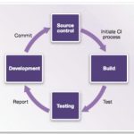
A familiar refrain in software development, as much as in hardware development, is that the size and complexity of projects continues to grow as schedules shrink and expectations of quality can increase dramatically. A common approach to managing this challenge in software programs is agile development practices and one aspect of that approach is continuous integration (CI). In CI any checkin by any developer triggers in effect a production build and test. Broken builds are immediately flagged to all developers to encourage quick correction to deviations from a working build rather than allowing hidden integration issues to accumulate. CI is primarily an engineering discipline, but naturally it benefits greatly from automation support. Popular open-source tools in this domain include Jenkins for CI automation and Linaro LAVA for test build/automation.
Agile methods in general and CI in particular were developed as software engineering practices assuming a stable hardware platform. But how do you apply these concepts when, as in many embedded applications, that hardware is still in development? Hardware-based prototype models are available too late in product development or are too slow (or both), so software developers depend heavily on (software-based) virtual prototype (VP) models which model hardware behavior with just enough detail to ensure that software running on the VP will behave similarly on the ultimate hardware, yet can still run at near real-time speed.
Synopsys Virtualizer Development Kits (VDKs) provide the kind of VP platform you need to connect to CI frameworks. VDKs can be developed from scratch starting from (high-level) transaction-level models, or you can start from one of several pre-built solutions such as the family of VDKs for ARM processors which you can then customize to match your specific design configuration. The ARM VDKs, for example, provide out-of-the-box support for Linux and Android, plug-n-play with software debuggers from ARM, Lauterbach and GNU and reference virtual prototypes for several DesignWare interface IPs, among many other features. VDKs aim to get you up and running quickly with a full-functioned VP, requiring a minimum of tuning on your part.
Once you have your VDK, you can integrate it into a CI framework. For more technical details, see the link at the end of this blog. Here I want to touch on how VDKs integrate into CI testing frameworks and what that integration enables. Each VDK provides interfaces to connect input stimuli from the framework to the VDK and output information from the VDK back to the framework. Control commands for objectives like run-control can also be communicated between the framework and VDK via a TCP/IP connection to a scripting layer within the model.
VDKs provide support for many types of analysis but a couple are especially interesting here. Let’s start with support safety standards per ISO 26262. It has been said that there are more lines of code in a Ford Fusion that there are in a Boeing 777. You’re not going to develop, maintain and enhance that kind of code-base in a waterfall model; you have to use something like CI. Also safety standards compliance for that code has to be based on in-the-loop testing. Again, software developers don’t have the hardware available to do that testing until late in the development cycle but with VDKs they can do Fault Mode and Effect Analysis (FMEA) using virtual models, which they can instrument through the (scriptable) fault injection capability provided in VDKs. They can inject faults on memory content, registers and signals, or on the loaded embedded software; this is completely non-intrusive, requiring no modification to the embedded software. Additionally, the scripting layer provides full control to define complex scenarios and corner-cases based on complex triggers which may be difficult to easily reproduce in the real hardware. This capability is completely deterministic so fault scenarios are repeatable and can be included in regression testing.
In a similar vein, code coverage is a key metric in the completeness of any software testing. VDKs provide an on-target code coverage measurement solution, not requiring software instrumentation. In both this case and the fault coverage case, coverage can be integrated into CI coverage, using plugins like Cobertura.
You might possibly have missed one rather important point in all of this. Of course software teams are able to develop and continuously integrate software based on VDK platforms long before the hardware is ready. But because the VDK is also software, they can do so in parallel; they don’t need to plug into hardware prototypes for development or CI testing. That’s rather important when you want to implement CI. Imagine having all the CI infrastructure setup then having to stand in line to get your turn on a hardware prototyper; that would rather defeat the object of the exercise. But you can have as many VDKs running simultaneously as you need; VDKs make CI possible when hardware is also under development.
You can read more about how VDKs can support continuous integration HERE.
CEO Interview: Mike Wishart of efabless
This is the 12th in a series of interviews we will do with executives inside the fabless semiconductor ecosystem. Michael Wishart, efabless Chairman and CEO, retired from Goldman Sachs after thirty years covering the technology industry as an investment banker. Michael is currently on the board of Cypress Semiconductor and before that he was on the Spansion board. Mike and I talk about the upcoming eFabless Design Challenge.
TELL US ABOUT EFABLESS AND ITS MODEL?
efabless corporation is building a community of analog and mixed signal engineers and equipping them with tools and an innovative crowdsourcing business model to solve the critical electronic enablement bottleneck to IoT and smart hardware design. IoT brings with it an explosion of consumer and industrial designs, each of which requires a unique combination of sensor, analog and mixed signal electronics to connect their digital “smarts” with the world in which they operate. IoT is therefore a very customized world requiring intensive collaboration between a multitude of visionaries with creative product ideas and a multitude of equally creative experts in electronics. This is a new type of ecosystem that is not easily addressed by conventional methods of electronics design and traditional IC companies. We employ crowdsourcing models proven deliver creative, customized solutions in other aspects of system design and adapt these models to the specific requirements of IP and ICs.
At efabless:
- Customers will pose requests for unique ICs and IP which are then filled by community members.
- Community members will design IP and ICs with no upfront cost and sell or license them through our marketplace.
An important element of crowdsourcing is the use of the Design Challenge, which proves the feasibility of the model, solves unique sets of problems and engages and attracts community members. Today we have approximately 600 community members from 30 countries. We look to grow this community as we roll out design challenges for IP and ICs and enable new categories of sensor and mixed signal intensive hardware products in areas like IoT, wearables and eHealth.
Mohamed Kassem, ex of TI, and I had independently pursued the idea of crowd sourcing hardware and IC development and innovation, until introduced by VC Lucio Lanza who saw our complementary experiences and had his own vision of the eBay of analog IP. Jack Hughes has also been a powerful influence on our company and has been intimately involved in the building of our model. Jack, a director and a founding investor in efabless, was the founder and CEO of the extremely successful software crowd sourcing company, Topcoder. The four of us are blessed to lead a great team of successful and experienced open source thought leaders, technologists and executives.
WHY ARE THE EFABLESS DESIGN CHALLENGES INTERESTING?
efabless is dedicated to democratizing the design process and believes that results will speak for themselves. Challenges are powerful, effective, fun ways to solve real problems and they prove the feasibility of crowdsourced design of ICs and IP. We host Design Challenges where community members design and compete against other community members for cash prizes, badges acknowledging capability and ratings of relative performance. The efabless Challenges are “open” to all comers, with only minimum exceptions (Designers must be of minimum age, have no contractual restrictions and not be from one of the limited number of “restricted countries”). The fact is that “open” is commonplace and even essential to a design challenge and have been fundamental to design challenges in other disciplines. Until efabless, though, design challenges have been virtually unheard of in IC design because IC design and manufacture is too expensive and restricted to truly attract any and all comers. We solve this. The efabless design environment provides our community with everything needed to design, verify and deliver analog and mixed signal designs. The design flow is based on foundry supplied design kits and proven open source tools, which allows contestants to design for no upfront cost, and monetize the results of their efforts. We protect the underlying process technology of the foundry which allows us to provide access to tools and IP without foundry NDA. Now a student in university can compete head to head with a 20-year veteran. A famous saying goes as follows: “The race is not always to the swift, nor the battle to the strong; but that is the way to bet.” Our emphasis is on the “not always”! Powerful, effective, fun …. FAIR.
HOW DOES THE EFABLESS DESIGN CHALLENGE WORK?
Here is how the Design Challenges work. We work with the Challenge Sponsor to create a spec for an IP to post as a challenge. Designers register on our site and, after reviewing a detailed description of the Challenge, accept the Challenge. The designer then completes and simulates the design and submits it to efabless. We then re-verify the design to confirm that it meets the overall spec of the Challenge and rate the qualifying designs by the relative success in the specific parameter or parameters of choice in the Challenge. The challenge winner selection is objective according to clearly specified and published criteria. Prizes are typically awarded to multiple designers.
In many cases, the Challenges will be sponsored by customers of efabless. In many cases, we will host our own Design Challenges.
WHAT IF I WIN? WHAT IF I LOSE? WHO OWNS THE DESIGNS?
efabless Design Challenges are design challenges with a twist. There are winners but there are no losers. Power to the designer! If you win, there is a cash prize and public acknowledgment of the achievement. efabless will publish on its websites the results and in many cases, so will the Challenge Sponsor. In certain cases, there may be a transfer of ownership to the Challenge Sponsor but in many cases, ownership will be retained by the designer.
Designs that are not chosen are owned by the designer and may be offered through our marketplace. A design that may not lead in the spec of the challenge may have other attributes that make it attractive to end-customers in the marketplace. We have all heard of the undrafted walk-ons that make it big in professional sports. Well, the “undrafted” designs have a second chance in the real marketplace where designs are licensed, bought and sold.
WHY SHOULD A COMPANY SPONSOR AN IP CHALLENGE?
Challenges are a very powerful means to combine product development with strategic marketing in one package. The Challenge format allows for a complete and compelling description of a unique or non-traditional problem. It maximizes the exposure to the global community, and hence the participation in the problem solving.
We see initial demand for the Challenge offering as a strategic and tactical solution for foundries in design enablement. Foundries tell us that they are concerned that their significant investments in differentiated process nodes go underutilized because of IP gaps in the associated IP portfolios. Challenges done through efabless will generate multiple IPs for a given spec, each with different and nuanced value propositions. Importantly, the efabless approach to design challenges provides a unique format to articulate the benefits of the node and of the foundry’s service to designers. Once the IP pump is primed with the Challenge process, various IPs will be created by the efabless community filling gaps identified by designers and customers.
TELL US ABOUT YOUR UPCOMING X-FAB DESIGN CHALLENGE
In the week of November 28, we will launch an industry first, a foundry sponsored design challenge for an IP. This will be the first of many for us to engage the community and deliver value to our customers. The X-FAB Design Challenge will feature a low power band gap. It will last for 12 weeks. All successfully verified designs will be entered into our marketplace. We will offer multiple cash prizes and feature the winning designs and designers on our website and in an ad, here on SemiWiki. We imagine that X-FAB will run its own promotion. Importantly, all designers will own the resulting IPs and all designs that pass our verification will be available to X-FAB customers through our marketplace. We and X-FAB see this initial Challenge as a first in what will be a series of Challenges of increasing complexity. Great for X-FAB, great for X-FAB customers, great for our community.
X-FAB is a leading foundry for analog/mixed signal ICs and has been a great supporter of efabless and our mission as we have built out our solution and community. The first process technology that is supported on our platform is X-FAB’s XH035 process on the 350 nm node.
WHAT NEXT?
We invite your readers to approach us with interesting ideas for new Design Challenges for IP. As we go forward, efabless will expand its capability to enable its growing community of analog and mixed signal to fill the custom mixed signal electronics gap in IoT and smart hardware design. Please visit our site and post a request or reach out directly to Mohamed (mkk@efabless.com) or me (mw@efabless.com).
Also Read:
CEO Interview: Chouki Aktouf of Defacto Technologies
Solido DA is One of Deloitte’s Fastest 50!

As a longtime EDA professional this really made my day. At a time where emerging EDA companies struggle for public validation, it warms my heart to see some very public recognition for an EDA job well done.
Deloitte, a leading Canadian professional financial services firm, announced the winners of their Technology Fast 50 program and low and behold #34 with 367.3% revenue growth is our own Solido Design Automation. Solido is known for championing variation aware design which is now a “must have” for competitive FinFET based semiconductor design.
Solido Design Automation makes Variation Designer, the world’s top CAD software for semiconductor variation analysis and debugging. Variation Designer is used to improve chip yield, improve performance, reduce die area, and reduce power consumption. It does this using a suite of technologies designed to provide fast, accurate measurement of variation effects and powerful tools for understanding and solving variation problems.
Our customers include most of the top semiconductor design companies in the world. Our user base currently spans well over 1000 production chip designers, and is growing quickly. Solido’s technology has been used to design chips that are in everything – phones, tablets, cars, TVs, PCs, credit cards – all kinds of products. It is becoming hard to find electronic devices manufactured in the last couple of years that do not include a chip that was designed using Solido’s software. We work with designers on mature and leading edge technologies; much of our production work is being done at sub-28nm processes, and we are now ramping up work on 7nm technologies.
Solido is headquartered in Canada, where our Product Development and Applications Engineering staff work together under one roof at Innovation Place in Saskatoon, Canada. We are expanding quickly to serve our growing customer base.
For the rest of the emerging EDA companies out there let me share with you the key to Solido’s success:
[LIST=1]
Strong EDA leadership means you can raise money. In his first EDA start-up (Analog Design Automation) Solido CEO Amit Gupta raised more than $20M in venture capital and government funding from funds including RBC Capital Partners, BDC Capital, Intel Capital, Synopsys Venture Fund, High Street Partners, and private investors. After 5 years ADA was acquired by Synopsys. In his second time around (Solido) Amit raised more than $10M in venture capital and government funding from funds including BDC Capital, Golden Opportunities Fund, and private investors. Strong leadership also means a focus on customer relationships. The best EDA CEOs that I have ever worked with spend the majority of their time with customers at all levels collaborating on all aspects of the business.
A scalable business model in EDA is hyper focused on ROI in every aspect of their business. For example, Solido employs more than 50 people in Saskatoon drawing the best and the brightest from the University of Saskatchewan every year. In 2017 Solido employees will more than double (100+) while the cost per engineer is a fraction of that in the US and turnover is the lowest I have seen in EDA.
Being in the right place at the right time takes vision and planning but most of all it takes stamina. Solido started the variation aware design mantra eleven years ago and now finds themselves the market leaders in a critical path of modern semiconductor design. Remember, Solido literally wrote the book on Variation-Aware Design of Custom Integrated Circuits.
Congratulations to my friends at Solido Design Automation, this award is well deserved and I know there will be more accolades to come, absolutely.