Laura Matz is also the Science & Technology Officer of Merck KGaA, Darmstadt, Germany. She has always been a key contributor to the growth in semiconductor materials, driving a strong R&D presence to enable business growth.
Laura is a strong advocate for young talent in science and engineering. As a leader, she builds teams to find innovative solutions to the problems facing humanity and implement them with the discipline and rigor to create the greatest impact. In 2023, she joined SEMI Impact for Skills as a board member, a governance program to support upskilling and reskilling, to attract new talent, and to unlock EU and national/ regional funding. In addition, she is a board member of AIChE (American Institute of Chemical Engineers), a leading organization for chemical engineering professionals.
Laura has a Ph.D. in Analytical Chemistry from Washington State University and an undergraduate degree from the Indiana University of Pennsylvania.
Tell us a little bit about yourself and your company.
I have a dual role: CEO of Athinia and Chief Science & Technology Officer at Merck KGaA, Darmstadt, Germany.
Athinia is a secure data analytics platform for collaborating on relevant information from materials and equipment suppliers, device makers, and fabs in the semiconductor industry, with the goal of improving decision-making, minimizing quality deviations, and increasing efficiencies. With the proliferation of digital technologies, there is immense pressure on the semiconductor industry to produce with zero defects and deliver new innovations to market faster. The immense amounts of data produced today create opportunities for not only a single company but for the entire value chain to achieve excellence in production, innovation, and cost reduction. The challenge is that individual companies do not want to establish an isolated ecosystem given the prohibitive cost and time investments. The industry needs a standard in quality and manufacturing management, one based on a data ecosystem that allows for the secure and continuous sharing of data between many companies in the semiconductor industry. This is why we started Athinia.
What was the most exciting high point of 2023 for your company?
In 2023, Athinia expanded its industry collaboration platform, connecting material suppliers and device makers more deeply. This enlarged network through Athinia’s secure platform has led to greater transparency in the supply chain, heightened efficiency in operations, spurred innovation with shared knowledge, improved risk management, and fostered stronger business relationships. These developments have collectively boosted the industry’s capacity for technological advancement and market adaptability.
In 2023, Athinia achieved a significant milestone by fostering a novel industry collaboration. By integrating Tokyo Electron Limited (TEL) into Athinia’s data analytics platform, Athinia has expanded its network and created a secure platform for device makers and equipment suppliers to collaborate effectively. The collaboration has led to feasibility to further improve equipment performance, efficiency, and maintenance, created mutually benefits for both equipment and device makers. Athinia’s platform facilitates this by offering a secure environment for sharing insights, which adds value to the entire industry and sets a new standard for collaboration.
What was the biggest challenge your company faced in 2023?
The semiconductor industry is data extensive and large-scale organizations need to deal with vast amounts of data. To be able to derive insights from data that unlock efficiencies, shorten time to market, and improve quality, supply chain and sustainability, data needs to be shared across the value chain while ensuring stakeholders maintain control of their intellectual property. To enable successful data collaboration, unstructured content needs to be curated, data quality improved, and diverse sources integrated. However, many companies on the materials side do not employ data scientists.
How is your company’s work addressing this biggest challenge?
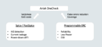
Athinia leverages Palantir Foundry for AI/ML and data analytics, focusing on integrating diverse data sources into a unified environment. This process involves effective ETL (Extract, Transform, Load) operations, data quality management, and building a reliable data foundation from various systems like manufacturing, quality control, and supply chain management. Using Foundry’s advanced AI/ML toolkit, Athinia develops and deploys models, with tools for no-code development and custom model creation via shared workspaces. These models drive operational insights, helping inform decisions through visualizations and actionable recommendations.
Palantir Foundry features walk-up usable applications such as Object Explorer, requiring minimal setup for immediate use and low maintenance. Foundry’s Workshop allows the creation of customized applications for specific workflows, with no/low-code builders for intuitive user interaction and minimal backend management. Its widget-driven interfaces cater to various skill levels, ensuring adaptability and scalability. Foundry’s open API architecture facilitates seamless integration with emerging technologies, while its decision orchestration layer bridges analytics with operational workflows, promoting continuous learning and adaptability.
Athinia is designed for scalability, handling increased data and model complexity without losing performance. It includes robust model governance and ethical AI practices, ensuring continuous model evaluation and responsible use with a human-in-the-loop approach. Collaboration is facilitated across teams, with an extensible architecture that integrates with other systems, turning data-driven insights into operational actions. Foundry enables Athinia to transform data into meaningful insights and actionable business outcomes, ensuring improved operational performance and yield.
In addition, Athinia is leveraging the strict data and security standards of the Foundry platform that are trusted by, e.g., the healthcare and defense industry. The Foundry platform’s robust security end-to-end architecture protects intellectual property and ensures customers always stay in control of their data. Customers own their data, Athinia has no access to it. With tailored and granular permissions, customers control who they share data with, how the data can be used, and for how long. Multi-level approval workflows ensure that data sharing follows your company’s data governance framework. Whenever parties are not willing to share raw process data, they have the possibility to obfuscate and normalize the data before it is being shared to protect sensitive data while maintaining its usefulness for advanced analytics such as machine learning.
What do you think the biggest growth area for 2024 will be, and why?
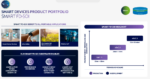
We are on the cusp of a revolution of AI adoption in all aspects of our global society. The drive for higher performance, enabling new AI solutions and faster AI insights for next-generation technologies in both memory and logic devices have never been more important. The material’s intelligence and development of advanced materials becomes really important in order to build a new generation of technologies. Over the next five years, the industry will experience a significant evolution in new nodes and facilities being built.
How is your company’s work addressing this growth?
Athinia is working with its customers to understand which materials will be needed, predict material ramps, accelerate qualification of materials with new production characteristics, and facilitate rapid innovation in the semiconductor industry through secure data sharing and advanced analytics enabling real-time insights.
Our secure data analytics platform processes diverse supplier data using machine learning to predict material performance. The platform offers real-time analytics for process monitoring and decision-making, with scalable data ingestion for adapting to growing data needs. Continuous improvement is achieved through a feedback loop, refining qualification models for efficiency. This results in a secure, adaptable, and sophisticated analytics platform that streamlines the materials qualification process.
The Athinia platform enables quick, informed decision-making, enhances collaborative research and development, and optimizes manufacturing processes. With predictive maintenance and digital twins, companies minimize downtime, and the platform’s robust security measures safeguard intellectual property. Athinia also aids in regulatory compliance and promotes sustainable manufacturing practices, supporting companies in staying competitive in a fast-paced market.
Furthermore, Athinia can enable tracking of the movement of materials and components throughout the supply chain. This transparency helps to ensure that all parts are legitimate and meet quality and emission requirements. By integrating data from all tiers of suppliers and establishing a unified ontology, Athinia helps customers gaining comprehensive visibility into key sustainability metrics like energy use, emissions, and waste generation, while still maintaining each node/tier intellectual property. Athinia’s real-time data processing and visualization capabilities allow continuous monitoring. Its AI/ML tools enable predictive analytics and scenario modeling, assisting in foreseeing and managing potential sustainability issues. The platform also aids in supplier assessments, regulatory compliance, and reporting. Additionally, the collaborative tools and machine learning insights drive continuous improvement and resilience in the supply chain, ensuring Athinia not only meets but also sets new industry benchmarks in sustainability. Athinia is founding member of the SEMI SCC, committed to working with high vertical sustainability via the value chain.
What conferences did you attend in 2023 and how was the traffic?
Athinia actively engaged with key semiconductor industry trends and developments. In 2023, Athinia participated in and presented pioneering data analytics examples at several industry conferences, including SEMICON West and CMC Critical Materials Council.
Will you attend conferences in 2024? Same or more?
I just came back from CES where I spoke on an AI panel in my role as Chief Science & Technology Officer at Merck KGaA, Darmstadt, Germany. Also in January, Athinia was recognized as the technology-enabled data collaboration platform at ISS in Half Moon Bay.
We will continue to intensively engage with key semiconductor industry trends and developments. Athinia is planning to attend the key semiconductor conferences to showcase the more recent industry innovation that resulted from data collaboration. We hope to see everyone at SEMICON West and other events.
Also Read:
Semiconductor Devices: 3 Tricks to Device Innovation
Investing in a sustainable semiconductor future: Materials Matter
Step into the Future with New Area-Selective Processing Solutions for FSAV