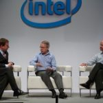
New TSMC 28nm Design Ecosystem!

New TSMC 28nm Design Ecosystem!
by Daniel Nenni on 05-28-2011 at 9:23 pm

TSMC rolled out the new reference flows for 28nm design as part of the Open Innovation Platform. The biggest surprise (to me) is that Cadence is STILL in the TSMC reference flows!

The updated TSMC OIP wiki is here, the Reference Flow 12.0 wiki can be found here, the AMS 2.0 reference flow wiki is here, and the official TSMC PR is here. The latest slides are included in the wikis for your viewing pleasure. TSMC customers can download the official materials at TSMC Online.

“TSMC customers can immediately take advantage of our 28nm advanced technology and manufacturing capacity while preparing for 20nm in the near future,” said Cliff Hou, TSMC Senior Director, Design and Technology Platform. “We have enabled customers to achieve their product design goals by closely collaborating with our EDA and IP partners to deliver a solid 28nm design ecosystem. In addition, the introduction of Reference Flow 12.0 and AMS Reference Flow 2.0 address critical design issues for the next generation of 28nm and 20nm applications.”

This announcement is a big fat hairy deal for several reasons:

[LIST=1]

  • Cadence is still partners with TSMC
  • 2.5D design
  • Emerging companies dominate
  • 28nm Power, Performance and DFM Design Enablement

    While Cadence executives pledge their allegiance to the open TSMC iPDK standard, Cadence product people continue to release INCOMPATIBLE products. The upcoming release of Virtuso GXL 6.1.5 (the high end version) will NOT allow a non SKILL based PDK to run (core dumps). My guess is that Virtuoso XL and L versions will soon follow. How will Cadence get away with this travesty? Big Cadence customers (80% of their revenue base) build their own PDK’s even if they use TSMC. Closed skill based PDK’s for Cadence customers versus open PDK’s for everyone else, great corporate strategy……. NOT! Cadence will be punished for this short sighted behavior by customers, it’s coming, believe it.

    TSMC will be the first fully 3D IC design capable foundry, no argument there. 2.5D design includes multiple dies to be integrated with a silicon interposer. Reference Flow 12.0 features new design capabilities in: floor planning, P&R, IR-drop, and thermal analysis to accommodate multiple nodes simultaneously. Also included is a new design for test methodology for 2.5D design.

    In addition to the “EDA Monopoly”, emerging companies continue to impregnate the TSMC reference flows:

    Apache, Arteris, AtopTech, Carbon Design System, CLK DA, Extreme DA, Sigrity, Sonics, SpringSoft, Berkeley DA, Ciranova, CST, EdXact SA, CWS, Helic, Integrand, Lorentz, and my personal favorite Solido DA. EDA innovation comes from emerging companies so TSMC is doing the semiconductor design ecosystem a big fat hairy favor here by putting new tools in silicon. NO OTHER FAB DOES THIS!

    Timing degradation from wire and via resistance, power leakage, hotspot checking and fixing are also addressed in the reference flows. Smaller geometries bring bigger problems, believe it.

    TSMC has a monster booth at DAC with a partner pavilion. The TSMC DAC page is herewith:

    In case you don’t follow my Twittering @DanielNenni: TSMC and UMC will be back at 95% utilization in Q3 due to surging orders from the mobile internet craze. Most of which include ARM processors @ 40nm bearing the names: Snapdragon for Qualcomm, Tegra2 for NVIDIA, Armada for Marvell, and i.MX for Freescale at TSMC and OMAP4 for Texas Instruments at UMC. TSMC also has 100+ tape-outs coming in at 28nm so don’t expect excess fab capacity anytime soon.

    Taiwan was absolutely crazy this month. The drought continues, the streets of Hsinchu were packed with scooters, and at2pmon Wednesday there was a bombing drill. For 30 minutes we were required to stay inside while the streets were cleared. This has been going on for years and it reminded me of elementary school where we hid from atomic bombs (cold war) under our desks.

    Don’t forget to share this on LinkedIn:


  • TSMC Conference Call is a 6.5 on the Richter Scale

    TSMC Conference Call is a 6.5 on the Richter Scale
    by Daniel Nenni on 04-28-2011 at 12:17 am

    TSMC continues to drive the economic recovery with impressive Q1 numbers and an even more impressive Q2 and Q3 outlook. TSMC is my economic bellwether due to its diverse customer base and shear volume of consumer electronics silicon. The big surprise in the 1 hour Q1 conference call is a new Giga Fab (#15) ground breaking this year for added 40nm and 28nm production. This is TSMCs 3[SUP]rd[/SUP] Giga Fab which can produce 100,000+ wafers per month. So the TSMC strategy is clear, economies of scale, out produce your competitors and prepare for a wafer price war like no other.

    Coincidently I’m in Taiwan this week and yes, another earthquake hit, this time just hours before my arrival. As I blogged before, my Taiwan friends think I bring California earthquakes to Taiwan. My first was in September 1999, then again in July 2009. This year my earthquake karma is better. My Taiwan trips usually start with a 6am Monday morning arrival and a 7pm Thursday evening departure. My March trip ended early so I was in the air for the Thursday 6.9 earthquake. This trip started late with a Monday evening arrival so again I was in the air for the Monday 6.5 quake. I am now required by the Taiwan government to give 30 days advance notice upon my arrival so they can be earthquake prepared. No Fab damage was reported after Monday’s quake.

    The other big surprise for some is that TSMC 28nm production will start the end of Q2 2010. Dr. Shang-Yi Chiang, Vice President of TSMC R&D, confirmed that “TSMC plans to start trial-run production of 28-nanometer technology in June”, which is what he told me personally at our April 13th meeting. GlobalFoundries told me 28nm trial-run production is scheduled for Q1 2011 so TSMC is still 6 months ahead. GlobalFoundries also announced a 20nm node, again following TSMC.

    On the financial side, TSMC’s balance sheet can be found here, conference call materials here, management report here, earnings release here, and the conference call transcript here. The most interesting numbers to me are the Revenue by Applications which showed gains in communications and consumer electronics but a decrease in computers. Also Revenue by Technology: Advanced process technologies (0.13-micron and below) accounted for 71% of wafer revenues, 90-nanometer process technology accounted for 17% of wafer revenues, 65-nanometer 27%, and 40-nanometer jumped to 14% of total wafer sales.

    Moving forward, TSMC expects Q2 sales to reach T$100-102 billion from Q1 T$92.19 billion, beating market expectations. TSMC also said second-quarter gross profit margin should be 48-50 percent, compared with the 47.9 percent in the previous three months. TSMC expects an operating profit margin of 36.5-38.5 percent, versus the first quarter’s 37%.

    Clearly semiconductor manufacturing outsourcing is moving forward at a rapid pace. TSMC Chairman and CEO Morris Chang forecast 2010 sales in the global semiconductor market (+22%) will again be outpaced by foundry market growth (+36%). Unfortunately, with all electronics sectors showing stronger than seasonal demand, wafer rationing is amongst us.

    According to Morris Chang:

    “We have been building capacity as fast as we could and the result is still that demand is 30 per cent greater than supply”

    “TSMC’s plants are likely to continue to run at full capacity for the next year”

    “In the very short term [over the next nine to 12 months], it makes no sense to ask our customers to give us more orders [because of the lack of capacity]“

    “Perhaps in a year or two our utilisation will drop below 100 per cent, but we’ll take that in stride”


    Process Design Kits: PDKs, iPDKs, openPDKs

    Process Design Kits: PDKs, iPDKs, openPDKs
    by Paul McLellan on 03-24-2011 at 5:28 pm

    One of the first things that needs to be created when bringing up a new process is the Process Design Kit, or PDK. Years ago, back when I was running the custom IC business line at Cadence, we had a dominant position with the Virtuoso layout editor and so creating a PDK really meant creating a Virtuoso PDK, and it was a fairly straightforward task for those process generations.

    The PDK contains descriptions of the basic building blocks of the process: transistors, contacts etc and are expressed algorithmically as PCells so that they automatically adjust depending on their parameters. For example, as a contacted area gets larger, additional contact openings will be created (and perhaps even removed, depending on the design rules).

    Two things have changed. Firstly, Virtuoso is no longer the only game in town. All the major EDA companies have their own serious offerings in the custom layout space, plus there are others. But none of these other editors can read a Virtuoso PDK which is based on Cadence’s SKILL language. The second thing that has changed is that design rules are so much more complex that creating the PDK is a significant investment. Creating multiple PDKs for each layout editor is more work still, and work that doesn”t really bring a lot of value to either the foundry or the user.

    Since Cadence isn’t about to put its PDKs (and PCells) into the public domain as a standard everyone can use, a new standard was needed. The Interoperable PDK Libraries Alliance (IPL), working with TSMC, standardized on using Ciranova’s PyCell approach (based on Python rather than SKILL) and created the iPDK which is supported by all the layout editors (even Virtuoso, at least unofficially).

    But if one standard is good, two is even better right? Well, no. But there is a second portable PDK standard anyway called OpenPDK, being done under the umbrella of Si2, although the work just started last year and hasn’t yet delivered actual PDKs.

    There is a lot of suspicion around the control of these standards. iPDK is seen as a TSMC standard and, as a result, Global Foundries won’t support it. They only support the Virtuoso PDK, which seems a curious strategy for a #2 player wanting to steal business from TSMC and its customers. Their Virtuoso-only strategy makes it unnecessarily hard for layout vendors to support customers who have picked other layout systems.

    Si2 is perceived by other EDA vendors as being too close to Cadence (they also nurture OpenAccess and CPF, which both started off internally inside Cadence) and so there is a suspicion that it is in Cadence’s interests to have an open standard but one that is less powerful than the Virtuoso PDK. Naturally, Cadence would like to continue to be the leader in the layout space for as long as possible.

    It remains to be seen how this will all play out. It would seem to be in the foundries interests to have a level playing field in layout systems, instead of a de facto Cadence monopoly. TSMC clearly thinks so. However, right now Global seems to be doing what it can to prop up the monopoly, at least until OpenPDK delivers.

    lang: en_US


    Moore’s Law and Semiconductor Design and Manufacturing

    Moore’s Law and Semiconductor Design and Manufacturing
    by Daniel Nenni on 03-12-2011 at 4:51 am

    The semiconductor design and manufacturing challenges at 40nm and 28nm are a direct result ofMoore’s Law, the climbing transistor count and shrinking geometries. It’s a process AND design issue and the interaction is at the transistor level. Transistors may be shrinking, but atoms aren’t. So now it actually matters when even a few atoms are out of place. So process variations, whether they are statistical, proximity, or otherwise, have got to be thoughtfully accounted for, if we are to achieve low-power, high-performance, and high yield design goals.

    "The primary problem today, as we take 40 nm into production, is variability,” he says. “There is only so much the process engineers can do to reduce process-based variations in critical quantities. We can characterize the variations, and, in fact, we have very good models today. But they are time-consuming models to use. So, most of our customers still don’t use statistical-design techniques. That means, unavoidably, that we must leave some performance on the table.”Dr. Jack Sun, TSMC Vice President of R&D

    Transistor level design which lnclude Mixed Signal, Analog/RF, Embedded Memory, Standard Cell, and I/O, are the most susceptible to parametric yield issues caused by process variation.

    Process variation may occur for many reasons during manufacturing, such as minor changes in humidity or tempature changes in the clean-room when wafers are transported, or due to non uniformities introduced during process steps resulting in variation in gate oxide, doping, and lithography; bottom line it changes the performance of the transistors.

    The most commonly used technique for estimating the effects of process variation is to run SPICE simulations using digital process corners provided by the foundry as part of the spice models in the process design kit (PDK). This concept is universally familiar to transistor level designers, and digital corners are generally run for most analog designs as part of the design process.

    Digital process corners are provided by the foundry and are typically determined by Idsat characterization data for N and P channel transistors. Plus and minus three sigma points maybe selected to represent Fast and Slow corners for these devices. These corners are provided to represent process variation that the designer must account for in their designs. This variation can cause significant changes in the duty cycle and slew rate of digital signals, and can sometimes result in catastrophic failure of the entire system.
    However, digital corners have three important characteristics that limit their use as accurate indicators of variation bounds especially for analog designs:

    • Digital corners account for global variation, are developed for a digital design context and are represented as “slow” and “fast” which is irrelevant in analog design.
    • Digital corners do not include local variation effects which is critical in analog design.
    • Digital corners are not design-specific which is necessary to determine the impact of variation on varying analog circuit and topology types.

    These characteristics limit the accuracy of the digital corners, and analog designers are left with considerable guesswork or heuristics as to the true effects of variation on their designs. The industry standard workaround for this limitation has been to include ample design margins (over-design) to compensate for the unknown effects of process variation. However, this comes at a cost of larger than necessary design area, as well as higher than necessary power consumption, which increases manufacturing costs and makes products less competitive. The other option is to guess at how much to tighten design margins, which can put design yield at risk (under-design). In some cases under and over-design can co-exist for different output parameters for a circuit as shown below. The figure shows simulation results for digital corners as well as Monte Carlo simulations which are representative of the actual variation distribution.

    To estimate device mismatch effects and other local process variation effects, the designer may apply a suite of ad-hoc design methods which typically only very broadly estimate whether mismatch is likely to be a problem or not. These methods often require modification of the schematic and are imprecise estimators. For example, a designer may add a voltage source for one device in a current mirror to simulate the effects of a voltage offset.

    The most reliable and commonly used method for measuring the effects of process variation is Monte Carlo analysis, which simulates a set of random statistical samples based on statistical process models. Since SPICE simulations take time to run (seconds to hours) and the number of design variables is typically high (1000s or more), it is commonly the case that the sample size is too small to make reliable statistical conclusions about design yield. Rather, Monte Carlo analysis is used as a statistical test to suggest that it is likely that the design will not result in catastrophic yield loss. Monte Carlo analysis typically takes hours to days to run, which prohibits its use in a fast, iterative statistical design flow, where the designer tunes the design, then verifies with Monte Carlo analysis, and repeats. For this reason, it is common practice to over-margin in anticipation of local process variation effects rather than to carefully tune the design to consider the actual process variation effects. Monte Carlo is therefore best suited as a rough verification tool that is typically run once at the end of the design cycle.

    The solution is a fast, iterative AMS Reference Flow that captures all relevant variation effects into a design-specific corner based flow which represents process variation (global and local) as well as environmental variation (temperature and voltage).

    Graphical data provided by Solido Design Automation‘s Variation Designer.


    TSMC 2011 Technology Symposium Theme Explained

    TSMC 2011 Technology Symposium Theme Explained
    by Daniel Nenni on 03-09-2011 at 6:49 pm

    The 17[SUP]th[/SUP] Annual TSMC Technology Symposium will be held in San Jose California on April 5[SUP]th[/SUP], 2011. Dr. Morris Chang will again be the keynote speaker. The theme this year is “Trusted Technology and Capacity Provider”and I think it’s important to not only hear what people are saying but also understand why they are saying it, so that is what this blog is all about.

    You can bet TSMC spent a lot of time on this theme, crafting every word. When dealing with TSMC you have to factor in the Taiwanese culture which is quite humble and reserved. Add in the recent semiconductor industry developments that I have been tweeting and I offer you an Americanized translation for “Trusted Technology and Capacity Provider”, a phrase made famous by the legendary rock band Queen “We are the Champions!”

    DanielNenni #TSMC said to make 40nm Chipset for #INTEL’s Ivy Bridge CPU:
    http://tinyurl.com/46qk89b March 5

    DanielNenni #AMD contracts #TSMC to make another CPU Product:
    http://tinyurl.com/4lel5zy March 2

    DanielNenni #Apple moves #SAMSUNG designs to #TSMC:
    http://tinyurl.com/64ofq67 February 15

    DanielNenni #TSMC 2011 capacity 2 rise 20%
    http://tinyurl.com/4j5v6qtFebruary 15

    DanielNenni #SAMSUNG orders 1M #NVIDIA #TEGRA2 (#TSMC) chips:
    http://tinyurl.com/4aa2xo6February 15

    DanielNenni #TSMC and #NVIDIA ship one-billionth GPU:
    http://tinyurl.com/4juzdvd January 13

    TRUST in the semiconductor industry is something you earn by telling people what you are going to do then doing it. After inventing and leading the pure-lay foundry business for the past 21 years you have to give them this one: TSMC is the most trusted semiconductor foundry in the world today.

    TECHNOLOGY today is 40nm, 28nm, and 20nm geometries. Being first to a semiconductor process node is a technical challenge, but also a valuable learning experience, and there is no substitute for experience. TSMC is the semiconductor foundry technology leader.

    CAPACITY is manufacturing efficiency. Capacity is yield. Capacity is the ability to ship massive quantities of wafers. From MiniFab to MegaFab to GigaFab,TSMC is first in semiconductor foundry capacity.

    Now that you have read the blog let me tell you why I wrote it. The semiconductor foundry business is highly competitive which breeds innovation. Innovation is good, I like innovation, and would like to see more of it. Other foundries take note, the foundry business is all about TRUST, TECHNOLOGY, and CAPACITY.

    Right now I’m sitting across from Tom Quan, TSMC Design Methodology & Service Marketing, in the EVA Airways executive lounge. Both Tom and I are flying back from Taiwan to San Jose early to participate in tomorrow’s Design Technology Forum. Tom is giving a presentation on “Successful Mixed Signal Design on Advanced Nodes”. I will be moderating a panel on “Enabling True Collaboration Across the Ecosystem to Deliver Maximum Innovation”. I hope to see you there.


    Semiconductor Power Crisis and TSMC!

    Semiconductor Power Crisis and TSMC!
    by Daniel Nenni on 03-02-2011 at 8:48 pm

    Power grids all over the world are already overloaded even without the slew of new electronic gadgets and cars coming out this year. At ISSCC, Dr. Jack Sun, TSMC Vice President of R&D and Chief Technology Officer made the comparison of a human brain to the closest thing available in silicon, a graphical processing unit (GPU).

    Dr. Jack Sun is talking about the NVIDIA GPU, I believe, as it is the largest 40nm die to come out of TSMC. The human brain has more than 100 billion neurocells (cells of the nervous systems). 100 billion neurocells consume 20 watts of power versus 200 watts for an equivalent amount of transistors in silicon. The bottom line is that semiconductor technology is severely power constrained and he suggests that we must learn from nature, we must look at technology from the bottom up.

    “New transistor designs are part of the answer,” said Dr. Jack Sun. Options include a design called FinFET, which uses multiple gates on each transistor, and another design called the junctionless transistor. “Researchers have made great progress with FinFET, and TSMC hopes it can be used for the next generation of CMOS — the industry’s standard silicon manufacturing process,” Sun said.

    According to Wikipedia:
    The term FinFET was coined by UniversityofCalifornia,Berkeleyresearchers (Profs. Chenming Hu, Tsu-Jae King-Liu and Jeffrey Bokor) to describe a nonplanar, double-gate transistor built on an SOI substrate,[SUP][5][/SUP]based on the earlier DELTA (single-gate) transistor design.[SUP][6][/SUP]The distinguishing characteristic of the FinFET is that the conducting channel is wrapped by a thin silicon “fin”, which forms the gate of the device. The thickness of the fin (measured in the direction from source to drain) determines the effective channel length of the device.

    So now you know as much about a FinFET as I do.

    After the panel I had a conversation with Dr. Sun about power and looking at it top down from the system level. TSMC is already actively working with ESL and RTL companies (Atrenta) to do just that. Designers can optimize for power consumption and efficiency early in the design cycle at the register transfer level (RTL). Using commercially available tools, information about power consumption is available at RTL and can provide guidance where power can be reduced, in addition to detecting and automatically fixing key power management issues. Finding and/or fixing these types of problems later in the design cycle, during simulation or verification, can be costly and increase the overall risk of your design project finishing on time and within predetermined specifications.

    TSMC’s current Reference Flow 11.0 was the first generation to host an ESL/RTL based design methodology. It includes virtual platform prototyping built on TSMC’s proprietary performance, power, and area (PPA) model that evaluates PPA impact on different system architectures. The ESL design flow also supports high level synthesis (HLS) and ESL-to-RTL verification. TSMC also expanded its IP Alliance to include RTL based (soft) IP with Atrenta and others. Atrenta is known for the SpyGlass product which is the defacto standard for RTL linting (analysis). If you do a little digging on the Atrenta site you will find the Atrenta GuideWare page for more detailed information.

    But of course TSMC can always do more to save power and they will.


    Custom and AMS Design

    Custom and AMS Design
    by Daniel Payne on 02-21-2011 at 10:06 pm

    Samsung%203DIC%20Roadmap

    For IC designers creating full-custom or AMS designs there are plenty of challenges to getting designs done right on the first spin of silicon. Let me give you a sneak peek into what’s being discussed at the EDA Tech Forum in Santa Clara, CA on March 10th that will be of special interest to you:

    3D TSV (Through Silicon Vias) are gaining much attention and for good reason, they help to make our popular portable electronics quite slim and cost effective:

    Panelists from the following companies will discuss: Is 3D a Real Option Today?

    Rob Aitken, ARM Fellow, ARM
    Bernard Murphy, CTO, Atrenta
    Simon Burke, Distinguished Engineer, Xilinx
    Kuang-Kuo Lin, Ph.D., Director, Foundry Design Enablement, Samsung
    Juan Rey, Senior Engineering Director, Design to Silicon Division, Mentor Graphics

    The TSMC AMS Design Flow 1.0 was announced back in June 2010, so come and find out what’s changed in the past 9 months. In contrast, the digital flow is already at rev 11.0, which indicates a much more standardized approach to convergence in the digital realm.

    TSMC and Mentor will present on their AMS design flow:

    Tom Quan, Deputy Director of Design Methodology & Service Marketing, TSMC
    Carey Robertson, Director LVS and Extraction Product Marketing, Mentor Graphics

    Custom physical design is getting more interoperable with standards arising like OpenAccess:

    Learn how SpringSoft and Mentor are working together on signoff-driven custom physical design:

    Rich Morse, Technical Marketing Manager, SpringSoft
    Joseph C. Davis, Calibre Interface Marketing Manager, Mentor Graphics

    The EDA Tech Forum is free to attend, however you’ll want to signup to reserve your spot today. This is a full-day event with other sessions that may answer some nagging questions that you have about AMS design tools and flows.


    TSMC Raises The Semiconductor Bar With 450mm!

    TSMC Raises The Semiconductor Bar With 450mm!
    by Daniel Nenni on 02-03-2011 at 2:34 pm

    During the most recent conference call (transcript), TSMC not only beat revised estimates and announced record spending levels for 2011, Morris Chang also officially announced that a 450mm fab (Fab 12 Phase VI) is currently in the planning stages with target production @ 20nm in 2015. This is HUGE!

    According to Morris Chang:

    “For 2011, we expect the overall semiconductor market excluding memory to grow by about 7%.”

    I still say 7% is low and hold to my double digit prediction for semiconductor growth in 2011. New phones, tablets, and communications products will continue to drive semiconductors this year and next.

    We expect the foundry market to grow by about 15%, and we believe TSMC will grow more than 20% in U.S. dollars.”

    On the previous conference call Morris Chang predicted 14% growth for TSMC in 2011. In my follow-up blogs I predicted 20%+ 2011 growth for TSMC. Morris and I are now aligned so my prediction stands, TSMC will again post incredible numbers in 2011.

    “I want to say a few words about the 450-millimeter wafer manufacturing. Our first 450-millimeter pilot line is planned at our Fab12 Phase VI, starting with 20-nanometer technology. The timing of pilot line will be around 2013, 2014. Our first 450-millimeter production line is planned in around 2015, 2016,” said Morris Change, chief executive officer and chairman of TSMC

    This is déjà vu of the 200mm to 300mm transition. There was endless debate and lots of 300mm doubters until TSMC put a stake in the ground and started building the first 300mm fab. TSMC, Intel, Toshiba, and Samsung all publicly support the transition to 450mm citing both important technological advancements as well as significant capacity increases to meet the needs of future smartphone and tablet users around the world. One 450mm wafer should yield more than twice as much compared to today’s 300mm, and well over four times the number from yesterday’s 200mm.

    Unfortunately, once scheduled for a 2012 launch, the transition to 450mm wafers has been delayed due to both doubters and the financial meltdown. In 2009, the semiconductor equipment manufacturers, the enablers of 450mm wafers, lost more than $1B and released 30%-40% of their workforces. But with the current semiconductor industry upswing with foundries like TSMC and UMC operating at maximum capacity, 450mm semiconductor manufacturing is now in sight.

    GlobalFoundries is the last public 450mm foundry doubter. According to Thomas Sonderman, Vice President of manufacturing systems and technology at GlobalFoundries:

    “The rush to 450mm suggests a lack of ideas for improving fab productivity. At GlobalFoundries, we see a tremendous amount of headroom left in the 300mm process. We are tapping our expertise in lean manufacturing to extend the lifecycle of the industry’s current 300mm ….”

    In my opinion this is one of the main drivers for TSMC and 450mm, the GlobalFoundries challenge. It has definitely raised the innovation bar for TSMC and they have reacted accordingly. TSMC will build a 450mm fab and the semiconductor equipment manufactures will accommodate their most valued customer, believe it. Look for the FabClub (GlobalFoundries, Samsung, and IBM) to announce 450mm fabs in the coming months as they have no other choice if they want to compete with TSMC.


    TSMC Versus The FabClub!

    TSMC Versus The FabClub!
    by Daniel Nenni on 01-23-2011 at 11:00 pm


    The Common Platform Technology Forum last week was not well attended, less than half than the GlobalFoundries Conference. It was deja vu of previous CP forums but there were a couple of surprises to go with the disappointment. The lunch line was long, but fortunately I was escorted to the press lunch featuring VIP’s from Samsung, IBM and GlobalFoundries. Yes, I still blog for food.

    While I originally thought bringing back Common Platform from the dead was a good idea, attending the Forum definitely changed my mind. According to the presentations, Common Platform WAS wildly successful, but clearly it was not. Chartered Semiconductor WAS Common Platform and Chartered WAS purchased by GlobalFoundries for pennies on the total investment dollar, right?

    I would have rather them said, “Look, Common Platform has changed and this is why it WILL be successful from this day forward”. A little humility goes a long way, it also shows respect for the intelligence of the audience. My opinion now is that Common Platform should be laid to rest, dead is dead, no coming back. Only Zombies come back from the dead and no one wants a Common Zombie Platform.

    The surprises were twofold:

    (1) The FabClub will move to Gate-Last technology for 20nm and beyond. This is HUGE! Gate-Last and Gate-First refer to the point at which a metal gate electrode is dropped onto the wafer, before or after the high-temperature heating process. I spoke with Dr. Shang-Yi Chiang, Vice President of TSMC R&D, and asked why Gate-Last versus Gate-First for 28nm? TSMC actually had parallel 28nm projects: Gate-First, Gate-Last, and Poly-Gate. The winner was the Gate-Last 28nm implementation coupled with Restricted Design Rules (RDRs) due to scalability, performance, and yield. Dr Chang also stated that there is no density penalty using RDRs. When GFI starts yielding we will know for sure which implementation is best at 28nm but it looks like Shang-Yi was right. TSMC has 28nm Silicon with Altera, Nvidia, Xilinx, and AMD/ATI. The only silicon announced from GFI is ARM test chips.

    (2) The FabClub fabs (IBM, GFI, Samsung) are GDSII compatible but not mask compatible. This may be ignorance on my part, but I assumed you could move designs across foundries without millions of dollars in mask and other costs. GDS II compatible means design rule compatible, they can use the same DRC decks.

    The underlying theme I got from the forum was cost (yawn). The cost of future semiconductor research, development, and manufacturing will be too much for one foundry (TSMC) and will require a FabClub. Even if it was true it’s boring. An even better forum theme, one which I personally endorsed, would have been:

    “Common Platform
    is bringing the collaborative IDM semiconductor design and manufacturing culture to the merchant foundry business!” Daniel Nenni

    Samsung, IBM, and AMD are born and bred IDMs, GFI is a foundry. Take the best of both worlds and deliver. It’s a winner, believe it. A distinct advantage GlobalFoundries has over the competition and FabClub partners is communication. These guys have raised the bar! My advice is for IBM and Samsung to step aside and let GlobalFoundries lead the way.

    I’m in Taiwan, this week is the TSMC fiscal year end conference call with Morris Chang. Expect really good news: 12″ fabs are full, TSMC will hire more than 6,500 new employees in 2011, TSMC increased R&D expenses 50% and set an $8 billion+ CAPEX. Very big numbers considering semiconductor analysts are fortunetelling single digit semiconductor industry growth in 2011! FOOLS!


    The Future of Semiconductor Design!

    The Future of Semiconductor Design!
    by Daniel Nenni on 12-26-2010 at 10:15 pm

    Is EDA still an appropriate term for what we do? What applications will drive future semiconductor design innovation? Will further consolidation be required for EDA to thrive again? They are all good questions, questions that will hopefully be properly addressed at the EDAC CEO Forecast and Industry Vision event next week but here are my thoughts:

    Is EDA still an appropriate term for what we do? According to the most recent press releases:
    Synopsys, Inc. (Nasdaq: SNPS), a world leader in software and IP for semiconductor design, verification and manufacturing, today announced……

    Cadence Design Systems, Inc. (NASDAQ: CDNS), a global leader in electronic design innovation….

    Mentor Graphics Corporation (NASDAQ: MENT) is a world leader in electronic hardware and software design solutions………
    Magma® Design Automation Inc. (Nasdaq:LAVA), a provider of chip design software…..

    Not that EDA companies ever called themselves EDA companies in print, but I do see a disconnect here. One of the things I do for a living is provide background information to semiconductor industry investors. The foundries and their top customers are of BIG INTEREST, EDA and IP not so much. I have even conference called with analysts who have JUST attended EDA CEO presentations and they still don’t see the value in EDA. If you want to know the number one problem with EDA, that is it, communication. We really suck at it.

    What applications will drive future semiconductor design? That should be obvious after Christmas, EMBEDDED SYSTEMS! We got a new minivan for Christmas and you would not believe the electronics packages that are available today. Seriously, it’s like piloting a space shuttle. There has to be dozens of microprocessors and sensors embedded into this vehicle. Video cameras, collision avoidance, satellite, GPS, split screen DVD, electric doors, and disappearing seats just to name a few. Seriously, you push a button and the back seat automatically folds into the floor. The manual for this vehicle is hundreds of pages, hopefully one of my kids will read it someday.

    Currently embedded systems account for $200B+ of the $300B+ semiconductor revenues. That is if we can agree that an “embedded system” is an electronic device with a special purpose processor, including smartphones. The other $100B+ has general purpose processors driving them. Future semiconductor growth will come from the embedded side for sure.

    Will further consolidation be required for EDA to thrive again?Yes of course, I think we can all agree on that. My biggest concern however is the lack of EDA and IP start-ups. You will be hard pressed to find investors for semiconductor design. The top EDA companies are not helping much either. Remember when EDA partner programs were open? How about when the top EDA companies had incubators and VC funds? If the top EDA companies spent half as much time nurturing emerging companies as they do trying to kill them we would all be better off.

    Here’s the irony on the investment side, VC’s are spending billions of dollars on Facebook, Twitter, Zynga, and other mindless applications, but when it comes to the tools and IP that build the platforms? Pffft. How about when Google, Apple, and/or Oracle start buying ARM, Synopsys, and the other key semiconductor enablers? That will shake things up a bit and maybe we will remember where we all came from, START-UPS!