The fabless movement was instrumental in disaggregating the semiconductor industry. Vertical product development at the chip and system level has given way to a horizontal structure over the years. This organization of product development has been doing an admirable job of delivering extremely reliable products. However reliable for a phone is not reliable enough for an autonomous vehicle with a service life of up to and over a decade. This issue was recognized years ago and lead to the development of the ISO 26262 standard in 2011.
ISO 26262 deals with the electronic systems in a car, with the goal of avoiding systematic errors and faults, as well as helping to deal with random errors. It applies to non-critical systems such as infotainment and also to critical systems like brakes, steering and autonomous operation.
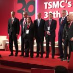
Electronic systems in cars are often produced by fables semiconductor companies and frequently incorporate 3[SUP]rd[/SUP] party IP. Applying ISO 26262 to products developed in a dispersed manner is leading to changes that are affecting every member of the supply chain. To explore these impacts Mentor hosted a panel discussion at DAC in Austin. The panel had representation from members of each element in the supply chain affected by ISO 26262.
At first glance it makes sense that Mentor would be on the panel as an embedded OS supplier, but in the context of ISO 26262, the design tool providers are also an essential link in the chain. Rob Bates, Chief Safety Officer for the Embedded Division, spoke on behalf of Mentor. Also on the panel was Volker Politz, VP Segment Marketing at Imagination Technologies, who talked about the changes necessitated for IP developers. Jim Eifert Automotive Architect at NXP provided insight from the automotive system integration perspective. Lastly, Lluis Paris, Director, Worldwide IP Alliance at TSMC shed light on how the foundries for fabless semiconductor companies have shifted the way they work in the automotive sector.
There was a round of introductory comments by each panelist. Jim from NXP said that a big benefit of the standard is that there is common terminology that buyers can use when speaking with suppliers. Lluis from TSMC talked about how the role of a fabless foundry has shifted from just supplying silicon to developing an automotive platform to enable and encourage ISO 26262. This stems from the need for more extensive sustaining engineering and additional product documentation among other things. TSMC has added the role of safety manager to their organization as part of this endeavor.
Volker from Imagination pointed out that now the IP provider is in the middle. In some ways they are partnered with their customer’s engineering department. Products fuse together external and internal IP and design work. The biggest change for him is that there is now a more formal way for them to work together. Rob from Mentor added that prior to ISO 26262 companies were just continuing to engage in their previous practices. The standard has really changed the way the companies involved operate. He cited the example of TSMC, who is rebuilding many aspect of how they deal with automotive designs from the ground up.
The first question put to the panel was, does IP have to be certified?
TSMC was quick to point out that IP does not have to be certified, but that the process for making the chip does. This arises because in many cases the applications for the IP are so large that the IP vendor can’t possibly know the use-case that is applicable. Imagination added that there is not really a certification for IP, but the vendors can help by delivering the necessary documentation with their IP. IP vendors can help contribute. NXP said that the car is what is certified, and the key is to turn over at each step of the development the correct documentation to facilitate this and create traceability.
The next question asked if embedded software should be considered IP.
Mentor responded by saying that the embedded software resides on the chip which is closer to the customer. Development tools are closely linked to the embedded code, so they too are tied to the standard in some way. NXP agreed that the embedded code needs to comply with the standard and wished there was more explicit requirements for development tools.
The next question asked if the car is ‘certified’ then what documentation is needed to create traceability up the chain from the components?
TSMC stated that the foundry has to do a larger number of things under ISO26262. These include special SPICE and reliability models, along with aging models. The car needs to be traceable after 18 years in case there is an issue down the road. The foundry needs to keep the process viable for a long time and may even potentially need to go back to the wafer info after many years. NXP added that the standard requires a quantitative approach to quality. As part of this it can go to the level of looking at parts per billion failure rates.
Mentor sees that ISO 26262 puts a burden on the tool users to qualify the tools they are using for design. However, realistically this is not something the tool users can take on by themselves. The tool vendor must play a role. This is why they created the Mentor Safe Program.
The panelists were asked, despite the increased level of work required, whether or not they saw benefits in following the process in terms of improved reliability and safety.
TSMC said that they were already doing many of the things that are needed. They feel that instead of a quality increase, what they are seeing is better lifecycle planning. Imagination answered by saying that they are seeing some improvements, but they are also seeing improved reusability. NXP followed by saying that their safety process was already working, but they now have a better documentation process. Mentor feels that the standard helps people look at what they were doing, and that it can only help.
Then came the question of how the standard should evolve. TSMC feels that the hardware side of the specification is comprehensive and stable. However, there is more work that will need to be done on the software side. Imagination would like to see more focus on real integrity. They feel it is important that people are committed to the process and this is the only way the data is reliable. They also expect additions in the area of security, which is at its core a safety issue. NXP amplified that concern by saying that security is absolutely a safety issue, and they are very concerned about hacking. Mentor also concurred that security is something that needs to be addressed more fully in the future versions of ISO 26262.
The panel closed with a question on what new things would be beneficial to the ecosystem. TSMC feels that there is a good ecosystem in place for silicon. They see further ecosystem work occurring in the customer infrastructure. Imagination reiterated the point that they felt that security should be a priority. Imagination said that the EDA companies can also do a lot to help. The more EDA players do – for instance fault injection – the easier it will be to meet the spec. NXP really wants to see chip level design flows made easier to qualify. If they can get a packaged solution it will reduce their need for spreadsheets.
Mentor agreed with this perspective and feels that EDA vendors can help make it possible to adhere to the standard more easily. For instance defect tracing analysis could be added, rather than it being an after-the-fact activity. Mentor sees value in adding capabilities to make it easier to qualify. At the end of the day Mentor feels these same practices and features have wider applicability. They want to move the process out of the automotive space. It could improve customer satisfaction in a wide range of products. Mentor did a great job of pulling together the panel participants and facilitating the discussion. With their Mentor Safe program, it is clear they are serious about automotive safety. For more information on Mentor’s work in this area, please look at their website.