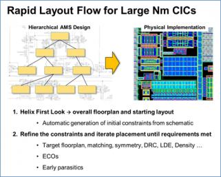
Ciranova presented a hierarchical custom layout flow used on several large advanced-node designs to reduce total layout time by about 50%. Ciranova itself does automated floorplanning and placement software with only limited routing; but since the first two constitute the majority of custom layout time, and strongly influence the remainder, the overall impact can be substantial. Designs sensitive to nanometer effects like Layout Dependent Effects (LDE) and poly density are particularly well suited to automation; one example was a 28nm, 40,000 device mixed-signal IP block which had been completely placed by one engineer in 8 days, including density optimization.

The Ciranova-enabled flow has two main phases. In the first phase, the software automatically generates a first-pass set of constraints for the entire design hierarchy, and a range of accurate floorplans. This phase is “push button” – it starts with a schematic and requires no intervention or user constraint entry. In the second phase, the user interactively refines the initial constraints, running and rerunning hierarchical placement until the entire layout matches the user’s floorplan targets and other criteria. The whole process is very fast; since the layouts are DRC-correct irrespective of rule complexity, tens of thousands of devices can be placed accurately in a few days. Ciranova’s output is an OpenAccess database which can be opened in any OA environment.
Two major advantages of this flow over normal schematic-driven-layout are (1) the DRC correct by construction aspect; and (2) the entire layout is optimized at once. This approach lends itself especially well to handling proximity-related effects like LDE, where the behavior of a given device changes depending on what happens to be nearby. Since Ciranova optimizes entire regions at once, multiple LDE spacing constraints are managed together.
In a TSMC design, TSMC provides tools at the schematic level to help a user identify LDE-sensitive devices in his or her schematic, and determine the relevant spacing constraints necessary for those devices to perform correctly. Ciranova then takes this information and produces a correct-by-construction layout which optimizes not only to the LDE directives but also to any other requirements: design rules, density, designer guidance such as symmetry, etc. Also, the approach is a general one and not limited to individual modules like current mirrors and differential pairs.

The diagram above includes a post-placement simulation study with alternate layouts of the same design: one with LDE rules applied, and one without (net result: the LDE-optimized placement clocks slightly faster). Most users never get to see a comparison like this, because hand layout takes so long that few people ever do it more than one way. But an automated flow makes this kind of study and tradeoff analysis easy.
Using this approach, even very large custom IC designs under very complex design rules can be done quickly; and typically at equal or better quality to handcraft, since much broader optimizations can be achieved than a human mask designer normally has time to explore.
Share this post via:


Comments
There are no comments yet.
You must register or log in to view/post comments.