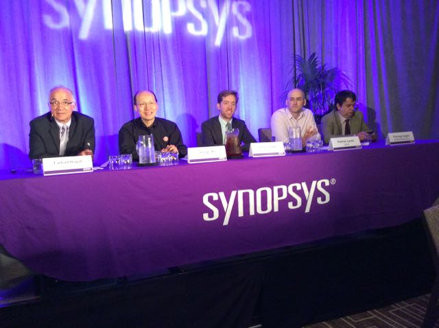
Actual users of circuit simulators told their design and simulation stories at DAC during a luncheon sponsored by Synopsys on June 8th. I always prefer to hear from a design engineer versus a marketing person about what tool they use for circuit simulation, and how it helps them analyze their design goals. This year there were engineers from TSMC, Altera, Xilinx and ST Microelectronics.

TSMC
Up first was Shaojie Xu from the Memory Design Products group, and his challenges were the design and characterization of a 2 port register file where they needed to trade-off simulation runtime versus accuracy, and get detailed parasitic extraction values. For timing and power analysis simulations they saw runtimes of 1-2 days when using 8 to 12 CPUs.
As they moved from the 28 nm to 10 nm process nodes there was an increase in parasitic extraction file size as the SPF files grew by a factor of 6X. Only the critical paths are cut out of the complete memory netlist in order to fit into the circuit simulator. They used CustomSim for SRAM characterizations to get the best runtime versus accuracy, and at 10 nm simulating across 80 PVT corners it took about 3 days to get complete results using 8 threads.
Altera
Ethan Howe talked about how they used the FineSim circuit simulator to validate their advanced-node designs for FPGA, ARM-based SoC and CPLD. TSMC and Intel Foundry are their two foundry partners. Circuit simulation trends include:
- Increased run times with smaller nodes like FinFET, compared to planar CMOS
- More parasitics used in FinFET designs, and the models get more complex
- Larger number of PVT corners required to center the design
- Lots of Monte Carlo simulations to account for process variations
While evaluating which circuit simulator to use, they found that FineSim was 2.5X faster than anything else at the same accuracy level. The fast simulation speed was attributed to good multi-core support and scalability on LSF. By doing a co-simulation between FineSim and Verilog (VCS) they saw an ADC case have speed improvements from 9 days to just 1.5 days.
Xilinx
AMS simulation was the focus of Patrick Lunch, and he talked about the design of their digitally-assisted ADC where they do voltage and temperature sensing on-chip in the Virtex series from 28 nm down to 16 nm. Their group also designed a 3D IC comprised of two 28 nm FPGA slices, while a DAC and ADC where implemented on 65 nm.
Digital verification was simulated with VCS, while AMS verification was done with the VCS AMS tool. Engineers used real number modeling and could swap out SPICE netlists with models. Requirements for AMS verification include:
- Support a UVM flow
- UVM + real numbers
- UVM + SPICE
- Self-checking of analog and digital
- Predictor models and assertions
There was a learning curve for UVM, but it was worth the wait because most AMS simulations completed within a day. They saw about a 3X run time improvement with VCS AMS versus their previous approach. Areas for improvement were:
- Writing predictor models in less time
- Want real ports in co-simulation flows
- More AMS assertions, checkers and source generators
STMicroelectronics
The final speaker was Pierluigi Daglio, someone that I met at DAC in 2010when hosting a panel discussion on SPICE. At ST they have a BCD (Bipolar-CMOS-DMOS) process and use the CustomSim simulator. On their SmartPower chips they can simulate the entire chip with CustomSim.
For system-level verification they use VCS AMS and can have either analog on top, or digital on top, depending on the methodology used for each design team. They are seeing simulation results about 2X faster now with CustomSim versus their previous simulator, and VCS AMS is up to 5X faster than before. By simulating with up to 16 cores they now see 3 day runs complete in just 1 day.
A PLL design in FDSOI at 28 nm would complete a Monte Carlo simulation before in 4 days using 1 core, while now with CustomSim they can use 8 cores and finish in under 1 day.
They write assertions to uncover any differences between the scoreboard and dynamic simulations to find failures. The asserts can be placed on either the digital or analog portions.
Summary
The cool thing with events like this DAC luncheon are that you can approach the speakers after their talk and have a further discussion, asking questions and finding out more details about how and why they used each of these different circuit simulation approaches.


Comments
0 Replies to “Circuit Simulation Update from #52DAC”
You must register or log in to view/post comments.