Semiconductor technology advances have a way of rewriting the rule book. As process geometries shrink, subtle effects graduate to mainstream problems. Performance curves can become inverted. And no matter what else occurs, low power demands are constantly reducing voltage and design margins along with it. Sometimes these problems can be solved by just being more careful, and sometimes they require a new way of approaching the problem altogether.
I had an opportunity to explore the latter case recently. I spent some time with Brandon Bautz, senior product management group director and Hitendra Divecha, product management director in the Digital & Signoff Group at Cadence. Both of these gentlemen have been working on advanced chip designs for more than 20 years, so I was in good hands.
We discussed the new Cadence Tempus™ Power Integrity Solution, or Tempus PI, for short. Why is this so interesting and important? Winding back the clock a bit, Hitendra began by explaining that customers had reported max frequency failures in advanced node silicon. The problem manifested with up to 10 percent performance degradation. This translates to hundreds of megahertz out of spec, so it gets attention. Thanks to low power/low voltage operation requirements, you can’t margin your way out of this problem. There just isn’t enough margin. So, what’s causing these failures, and what’s the fix?
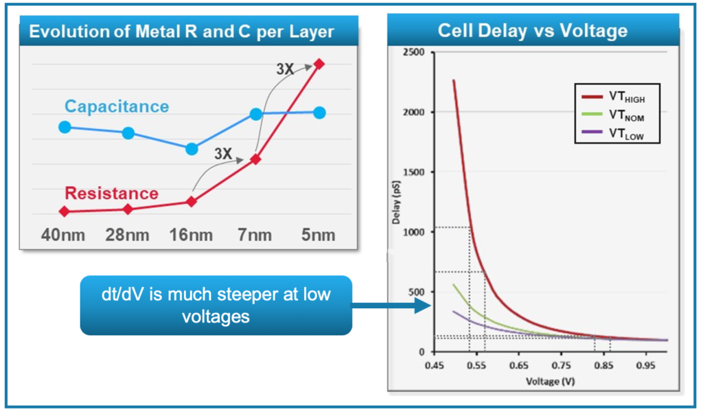
The root cause appeared to be related to localized IR drop, but there is a twist. As the process moved from 28nm to 7nm, conductor resistance through the power grids has increased by 10X. This means the traditional method of inserting decoupling capacitors to alleviate localized IR drop is no longer as effective. Also, the change in cell delay vs. voltage becomes much steeper at low voltages in advanced processes. This means a small IR drop will create a large change in timing. These effects are summarized in the diagram below.

Since timing and IR drop have a co-dependent relationship, the designer needs an automated method to simulate the design such that both timing and IR drop problems are simultaneously considered. A user-defined vector approach is difficult as enough vectors to find the problem will create huge runtimes. Random vector approaches create too many combinations as well. It’s a bit of “needle in a haystack” problem. Aggressor and victim nets also need to be considered if there is simultaneous switching and coupling.
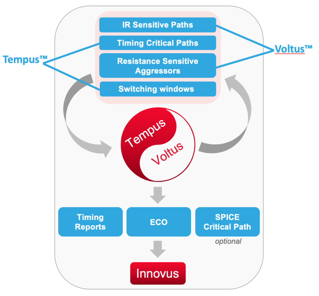
We then talked about the architecture of the Cadence signoff tools, specifically how Tempus™ Timing Signoff Solution and Voltus™ IC Power Integrity Solution have been built on a common database and runtime model from the start. By adding additional analysis capabilities to the mix, including machine learning techniques for vectorless stimulus, Tempus PI delivers IR drop-aware STA signoff—that is, voltage analysis that is timing-aware, and timing analysis that is voltage-aware. Using resistance, power, IR-drop and timing data, Tempus PI’s algorithm can identify voltage sensitive paths and potential aggressors. The result is a well-thought-out approach as to what timing paths and aggressors need to be carefully analyzed—not just random activity—solving the “needle in a haystack” problem.
Using the Innovus™ implementation System, timing and IR-drop problems can even be fixed with the ECO flow. As we continued our discussion it became clear the integrated nature of the Cadence tool suite was paying big dividends when it comes to addressing new problems that require simultaneous views to sort out. The figure below summarizes the complete flow.

The Cadence folks shared some results for the ECO flow on a CPU core design:
- Before: 1,334 IR-drop victims, 110.5 mV peak IR-drop voltage
- After: 87 IR-drop victims, 81.9 mV peak IR-drop voltage
93% fewer victims, 26% less peak IR with no setup/hold degradation. Impressive.
We concluded our discussion with a few customer case studies. I’ll cite two here, and they’re both 7nm designs.
Case 1: An extensive set of activity vectors was used by the customer to perform IR drop analysis. Of the top ten IR drop paths, four were confirmed as top risks with Tempus PI, but Tempus PI found six other top paths that were missed by the vector approach.
Case 2: Tempus PI identified 2,092 critical paths that would have been missed by the customer’s traditional derating method.
At this point, I’m a believer. By making IR drop analysis timing-aware, the new challenges of advanced technology can indeed be tamed. If you’re seeing these kinds of challenges, you should talk to Cadence.
Share this post via:


Comments
There are no comments yet.
You must register or log in to view/post comments.