SoC designs frequently have lots of different clock domains to help manage power more efficiently, however one side effect is that when the clock domains meet, i.e., in a Clock Domain Crossing (CDC), there’s the possibility of setup and hold time violations that can cause a flip-flop to become metastable. Synchronizer circuits are then employed to mitigate the metastability issue, although they add non-deterministic delays to the logic path. The challenge for an RTL simulator is to take these non-deterministic delays into account.

Siemens EDA wrote a white paper about this topic, and I’ll cover the traditional models for metastability effects, along with the model inside Questa CDC-FX.
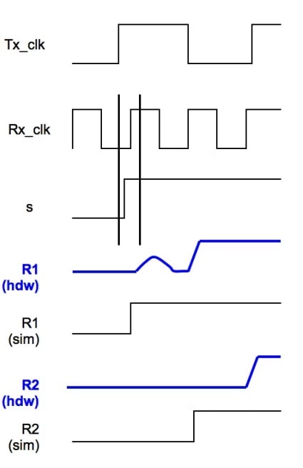
In the synchronizer example from above, metastability happens when signal S changes too close to the rising edge of rx_clk, and the output of R1 glitches towards a 1, but settles down to a 0 in hardware, while an RTL simulator shows R1 transitioning to a 1 much quicker. This hardware metastability from R1 then makes R2 switch one clock cycle later in hardware compared to the RTL simulator.
With the same synchronizer example when signal S arrives slightly after the rising edge of rx_clk then the output of R1 follows it to a 1 in hardware, while the RTL simulator waits until the next clock cycle for R1 to reach a 1 value, an effect called bleed-through. In this case the hardware transitions one cycle before the RTL simulator for both R1 and R2 signals.
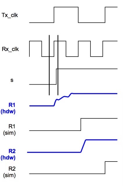
Both the extra-cycle delay and bleed-through cases only occur whenthe two clock domains, rx_clk and tx_clk have rising edges very close to each other in time. An ideal RTL simulator will match silicon for extra-cycle and bleed-through cases when:
- Violations of setup constraints cause simulator to add cycle delay
- Violations of hold constraints cause simulator to subtract a cycle delay
- CDC signals are modeled independently
- Registers with the same boundaries of clock domains have the same metastability effects
The RTL simulator industry has used several modeling methods to account for metastability effects.
- Clock jittering – random changes to timing of clock edge, globally or locally.
- 3 DFF synchronizer model – three registers instead of two.
- Propagation delay-based method – a random delay inserted before the synchronizer.
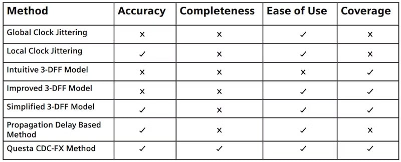
Pitfalls are shown for each of these modeling methods and their variations, which then leads to how the Questa CDC-FX method was developed to accurately simulate metastability effects.
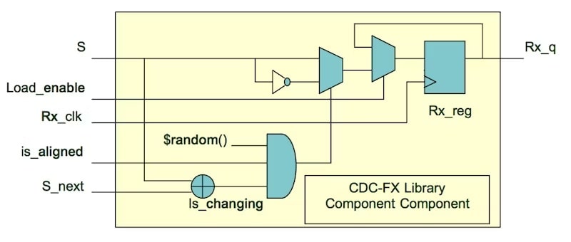
When the two clock edges – tx_clk, rx_clk, are closely aligned in time and signal S is changing, this circuit will pseudo-randomly invert S that gets loaded into register R1. This means that in RTL simulation the output is forced into R1:
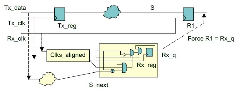
Both of the metastability effects introduced – extra-cycle delay and bleed-through – are modeled by inverting the value of S that gets loaded into R1. This CDC-FX circuit model can be automatically applied to every register that samples CDC signals.
Only the CDC-FX method satisfies all criteria for RTL matching silicon timing results.
Siemens recommends a complete CDC verification flow where the designer first runs a static CDC re-convergence analysis to remove any suspected re-convergence in the RTL. With netlist analysis three things are generated that are then used in subsequent steps:
- CDC assertions
- Coverage monitors
- Metastability effects injectors
Verification engineers then simulate tests as a second step using the CDC assertions and coverage monitors from step 1. Tests identified as being effective in step 2 are run with the metastability effects injectors enabled in step 3. The coverage monitors actually track activity at each bit of every CDC register, then provide statistics:
- Metastable cycles
- Delayed transitions
- Advanced transitions
- Inverted bits bitmap
If the design under test fails with metastability modeling in simulation, then the design must be debugged to identify the source of improperly re-converging CDC signals.
Summary
CDC verification for metastability effects is a necessary step for all designs using multiple clock domains. Siemens EDA has developed the Questa CDC-FX method to be complete and accurate, working on all CDC signals. The extra-cycle delay and bleed-through delay effects are injected so that RTL simulation matches silicon behavior.
Read the complete white paper online here.
Related Blogs
- The State of FPGA Functional Verification‘
- The State of IC and ASIC Functional Verification
- Achieving Faster Design Verification Closure
- Coverage Analysis in Questa Visualizer
- Faster Time to RTL Simulation Using Incremental Build Flows
- Siemens Offers Insights into Gate Level CDC Analysis
Share this post via:


Comments
There are no comments yet.
You must register or log in to view/post comments.