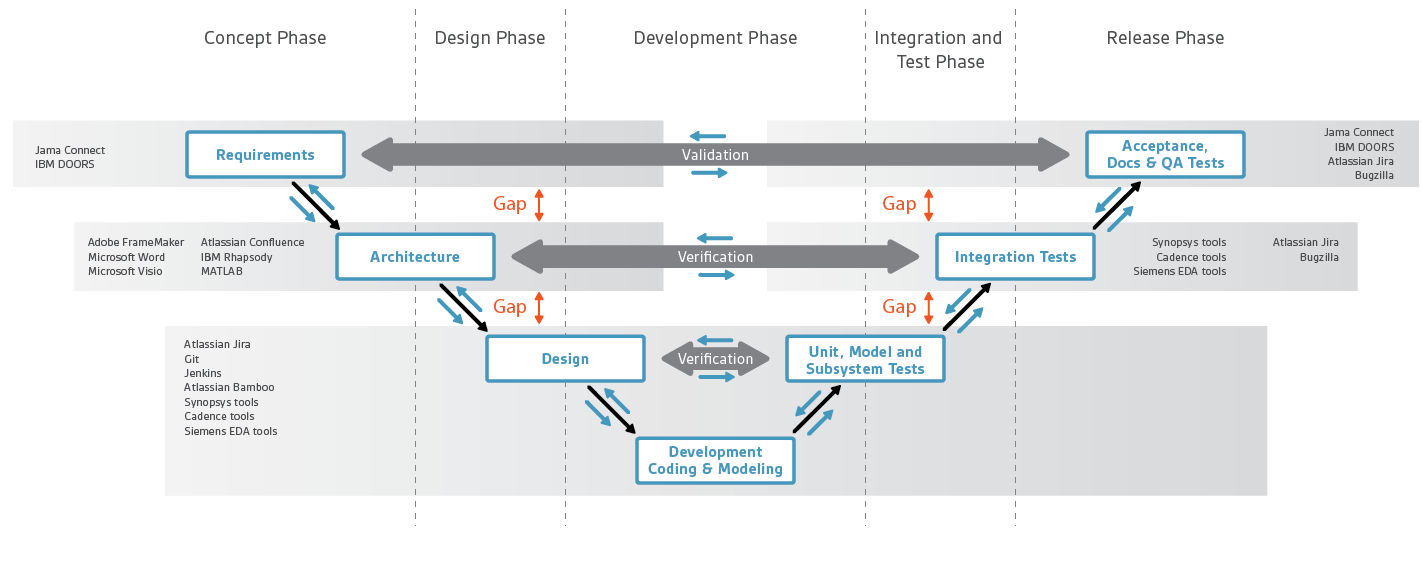
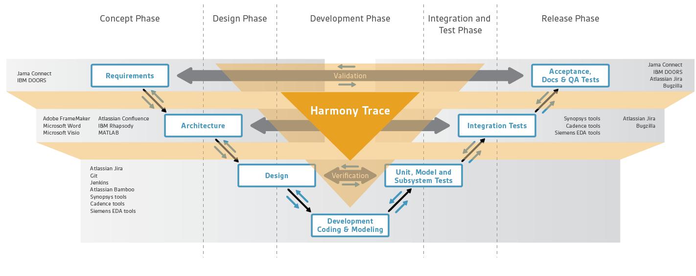
Since traceability and its relationship to ISO 26262 may be an unfamiliar topic for many of my readers, I thought it might be useful to spend some time on why this area is important. What is the motivation behind a need for traceability in support of automotive systems development? The classic verification and validation V-diagram is a useful starting point for understanding. The left arm of the V decomposes system design from concepts into requirements, architecture, and detailed design. The right arm represents verification and validation steps from unit testing all the way up to full system validation.

System development, verification and validation
Interdependency in system design
First, let’s talk about systems. A system is generally more than just a chip + software running on that chip. An example system is a car in which SoCs (chips + software) play multiple roles. There are many mechanical components in a car – engine, body structure, braking, airbags, seats and windows. All of which are enabled in various ways by electronic components: sensors to detect possible collisions, actuators to control brakes and steering, seat and window positions, communication and infotainment. These must work together as flawlessly as possible. Accomplishing this goal is managed through mountains of specifications, requirements lists and use-case definitions to ensure everyone is building and testing against the same expectations.
Car design depends heavily on reuse for the same reasons we face in SoC design – cost, schedule, quality, reliability. Plus, of course, safety. Which puts heavy constraints on interfaces between levels in the system. A new SoC must comply with multiple existing requirements in addition to meeting new requirements. The larger system and its software are very expensive to change and re-certify. New components like SoCs must fit the system requirements.
Mind the gaps
Now we’ve established that everything starts with specifications, requirements and use-cases, all non-negotiable expectations on a supplier; how does an SoC company map those into what they need to build? Going down the left arm of the V, requirements are managed in tools like IBM DOORS or Jama, and specifications might be in PDF and use-cases, perhaps in SysML. This information is very high level, not directly executable by an RTL design team.
An architect will map these requirements manually using her expertise into a more detailed specification, leveraging available IP and company differentiated skills. She will also optimize the architecture to meet performance, power and cost goals. The architect will use a different set of tools at this level, together with virtual modeling, to start early software development. That intent is then translated, usually manually, into the more familiar RTL design and modeling phase, where the full implementation is developed.
In the right arm of the V, verification and validation start with unit testing. These tests are built independently from development to maximize integrity of the testing. Subsystem and system testing follow, also independently developed for the same reason. Finally, full system validation runs against system software in a lab emulation of the full electronic system, perhaps even with some mechanical modeling.
There are gaps between all these stages, some well-intended, but gaps nonetheless. Humans must bridge these gaps; however, we are imperfect. We miss some things, we misinterpret others, and we don’t stay current with spec changes. You might hope for a universal modeling language to design out human fallibility, but that dream seems unattainable. Instead, we bridge the gaps with traceability – links connecting a higher-level requirement to lower-level implementation and tests of that requirement.
How traceability bridges the gaps
Without automation, the way you check correspondence between levels is through painstaking line-by-line checks between requirements and implementation. Tying up experts for days in performing those checks. Not so bad the first time, but as the design evolves, if the customer changes the specification or if multiple customers have conflicting requirements, periodically repeating that detailed level of check becomes very hard.

Bridging the gaps with Arteris® Harmony Trace™ traceability
A better solution would automate links between requirements and implementation, say a bus width or a register offset. Setup will require some initial effort, but then the integrity of that check persists through the design lifecycle and beyond. In a design review, you don’t have to slog through the documents every time; the tool will check automatically. If some parameter slipped out of compliance, you’d instantly know. You know you are still in compliance if the tool hasn’t raised any flags.
Traceability also gives you instant evidence you can show to somebody who’s going to check your work. Maybe your own internal safety team, maybe a customer demanding proof of compliance, maybe a safety process auditor. There’s another benefit. When something goes wrong (because this is engineering; something always goes wrong), you have an audit trail through traceability to help figure out what you should change in your process.
Traceability throughout the lifecycle
Traceability isn’t only important in the design phase. After the chip goes into production, when the auto OEM is running extensive tests, they may find a problem. In diagnosis, they want to trace back through software to hardware components. Can this problem be attributed to a deficiency in the requirements? Being able to trace quickly to a root cause can have a huge impact on corrective action and ultimately model release. Being able to provide quick turn-around and definitive evidence of compliance, or an unforeseen problem, can only enhance the reputation of a provider in the supply chain.
Arteris® Harmony Trace™
Is there such a solution available for SoC Product design teams? Arteris IP has now released its Harmony Trace product to automate and report on these links. Harmony Trace connects IP-XACT-based SoC assembly and the hardware/software interface to popular requirements management tools and to popular documentation formats. There is now an automated path to ensure compliance with those higher-level requirements and to be able to quickly demonstrate that compliance to customers and ISO 26262 auditors. To learn more, click HERE.
Also Read:
More Tales from the NoC Trenches
Smoothing the Path to NoC Adoption
Share this post via:


Comments
There are no comments yet.
You must register or log in to view/post comments.