Synopsys IP Designs Edge AI 800x100

Must See SoC IP!

Must See SoC IP!
by Daniel Nenni on 09-02-2013 at 5:30 pm


IP is the center of the semiconductor universe and nobody knows this better than Design and Reuse. The D&R website was launched in 1997 targeting the emerging commercial semiconductor IP market. Today, with more than 15,000 IP/SOC product descriptions updated daily, D&R is the #1 IP site matching customer requirements to IP products around the world.

D&R also hosts IP events including Semiconductor IP – SoC 2013 which will be the 22nd edition of the working conference on hot topics in the design world, focusing on IP-based SoC design and held in the French Alps (Grenoble) as well as Bejing, Shanghai, and Israel.

This event is the only worldwide dedicated semiconductor IP event. The satisfaction level of the attendees is high due to focused sessions and seminars. Over the year semiconductor IP has become Subsystems or Platforms. A natural applicative extension to IP-SoC will include a strong Embedded Systems track addressing a continuous technical spectrum from IP to SoC to Embedded System.

The competitive landscape of the Semiconductor IP Market, 2013 and Beyond!

Ganesh Ramamoorthy,Research Director, Gartner Inc.

Embedded design in the Age of Pervasive Computing

Richard York , Director of Embedded Processor Products, ARM

Open Innovation Platform (OIP): an ecosystem for innovation

Kees Jooss , Business Development Manager, TSMC

The New Tower of Babel – The Languages of Embedded Systems Design

Colin Walls, Mentor Graphics

Morphing Technology and Business Models at 100Gbps and Beyond

Marc Miller,Sr. Director of Marketing, Tabula

The flexible pathway to Flash IP

Christopher Neil Brown, Micro Chip

The conference is organized as a 2 day event:

  • The first day targeting architecture topics from IP to SoC solution to chip and chip set
  • The second day devoted to Embedded systems (from O.S to middleware to application software)

The program of both days is organized within within 4 tracks namely:

  • The well recognized Panel track on hot topics. These panels will address both IP and Embedded Systems to day challenges
  • Technical papers addressing the issues in the IP-based system design and in the Embedded System arenas
  • Visionary scientific seminarson key topics organized by gurus in the field, including invited state of the art academic presentations
  • Exhibitor track offering sponsored speaking opportunities for Companies willing to communicate their technical capabilities in greater depth ideas through technical presentations in one hour or in half-day workshops. Such a presentation slot may be a stand-alone demonstration of a development tool or technique

Important Dates
Deadline for submission of paper summary: September 28, 2013
Notification of acceptance: October 4, 2013
Final version of the manuscript: October 19, 2013
Working conference: November 6-7, 2013

Areas of interest:

Business models

  • IP Exchange, reuse practice and design for reuse
  • IP standards & reuse
  • Collaborative IP based design

Design

  • DFM and process variability in IP design
  • IP / SoC physical implementation
  • IP design and IP packaging for Integration

Quality and verification

  • IP / SoC verification and prototyping
  • IP / SoC quality assurance

Architecture and System

  • IP based platform
  • FPGA SoC
  • IP / SOC transaction level modelling
  • HW/SW integration
  • System-level prototyping and virtual prototyping
  • System-level prototyping and virtual prototyping

Embedded Software

  • IP based platfrom
  • Middelware
  • O.S

Reliability, Real-Time and Fault Tolerant Systems

  • IP reliability computation
  • Security IP
  • Real-time or Embedded Computing Platforms
  • Real-time Operating system

Paper Submission Procedure
To present a paper during the conference a summary of at least 3 pages is required for any submission. You may also apply to present a seminar paper on the topics that will be announced shortly. You can submit an electronic version of your extended abstract in a Word or PDF format using the Online Submission Form.

lang: en_US


Analog ECOs and Design Reviews: How to Do Them Better

Analog ECOs and Design Reviews: How to Do Them Better
by Paul McLellan on 09-02-2013 at 1:00 am

One of the challenges in doing a complex analog or mixed signal design is that things get out of step. One designer is tweaking the schematic and re-simulating, another is tweaking the layout of transistors, another is changing the routing. This is not because the design flow is messed up, but rather it reflects reality. If you wait until the schematic is finished to start layout, then you won’t finish in time. And besides, in a modern process, without detailed layout parasitics you can’t simulate the design accurately and so have the information needed to finish off the schematic. You need to make smaller and smaller changes and cross your fingers that everything converges on a layout that will give you the performance you require.

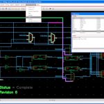
But this means that the schematic that goes with the current layout is not necessarily the most up-to-date. What is needed is a tool for comparing schematics and layouts. Obviously, these are stored in text or binary files which generally are not human readable and so a traditional diff program that simply tells you what changed in the file is useless. What is required is a visual diff that displays differences graphically, showing added transistors on the schematic or layout that has been moved. ClioSoft’s vdd (Visual Display Diff) is just such a tool.

VDD detects changes between different versions of schematics or layout including modifications to nets, instances, layers, labels and properties. Differences are highlighted graphically in the Cadence Virtuoso schematic or layout and also presented in a list. Users can select or step through the list. Selected changes are highlighted directly in the editor window and automatically zoomed to the area of interest. VDD has the option to ignore cosmetic changes so mere rearrangement or rerouting of wires will not be flagged. Users also can choose to invoke a hierarchical diff where all differences for the entire design hierarchy below the selected view will be flagged. VDD comes integrated with ClioSoft’s SOS design data management system but also can be deployed standalone with any other design management system or even if no design management system is being used.


ClioSoft have a game here called Spot the Diff where you have to find differences in schematics. Of course it is just a bit of fun but it has a serious purpose: finding changes by eye is really hard and time-consuming. That is why a tool like VDD is so essential.

Leading semiconductor companies including many in the top 10 are using VDD. You can find out more in an upcoming webinar presented by Srinath Anantharaman of ClioSoft, Managing Design Reviews and ECOs Efficiently. It is on Thursday September 12th at 11am Pacific. Details are here. Registration page is here.

Also Read

ClioSoft at GenApSys

VIA Adopts Cliosoft

Agilent ADS Users, Find Out About Design Data Management


A Brief History of TSMC OIP

A Brief History of TSMC OIP
by Paul McLellan on 09-01-2013 at 9:00 pm

The history of TSMC and its Open Innovation Platform (OIP) is, like almost everything in semiconductors, driven by the economics of semiconductor manufacturing. Of course ICs started 50 years ago at Fairchild (very close to where Google is headquartered today, these things go in circles). The planarization approach, whereby a wafer (just 1” originally) went through each process step as a whole, led to mass production. Other companies such as Intel, National, Texas Instruments and AMD soon followed and started the era of the Integrated Device Manufacturer (although we didn’t call them that back then, we just called them semiconductor companies).

The next step was the invention of ASIC with LSI Logic and VLSI Technology as the pioneers. This was the first step of separating design from manufacturing. Although the physical design was still done by the semiconductor company, the concept was executed by the system company. Perhaps the most important aspect of this change was not that part of the design was done at the system company, but rather the idea for the design and the responsibility for using it to build a successful business rested with the system company, whereas IDMs still had the “if we build it they will come” approach, with a catalog of standard parts.

In 1987, TSMC was founded and the separation between manufacture and design was complete. One missing piece of the puzzle was good physical design tools and Cadence was created in 1988 from the merger of SDA and ECAD (and soon after, Tangent). It was now possible for a system company to buy design tools, design their own chip and have TSMC manufacture it. The system company was completely responsible for the concept, the design, and selling the end-product (either the chip itself or a system containing it). TSMC was completely responsible for the manufacturing (usually including test, packaging and logistics too).

This also created a new industry, the fabless semiconductor company, set up in many ways to be like an IDM except for using TSMC as a manufacturer. So a fabless semiconductor company could be much smaller since it didn’t have a whole fab to fill, often the company would be funded to build a single product. Since this was also the era of explosive growth in the PC, many chips were built for various segments of that market.

At this time, the interface between the foundry and the design group was fairly simple. The foundry would produce design rules and SPICE parameters, and the design would be submitted as GDSII and a test program. Basic standard cells were required, and these were available on the open market from companies like Artisan, or some groups would design their own. Eventually TSMC would supply standard cells, either designed in house or from Artisan or other library vendors (bearing a underlining royalty model transparent to end users). However, as manufacturing complexity grew, the gap between manufacturing and design grew too. This caused a big problem for TSMC: there was a lag from when TSMC wanted to get designs into high volume manufacturing and when the design groups were ready to tape out. Since a huge part of the cost of a fab is depreciation on the building and the equipment, which is largely fixed, this was a problem that needed to be addressed.


At 65nm TSMC started the OIP program. It began at a relatively small scale but from 65nm to 40nm to 28nm the amount of manpower involved went up by a factor of 7. By 16nm FinFET half of the effort is IP qualification and physical design. OIP actively collaborated with EDA and IP vendors early in the life-cycle of each process to ensure that design flows and critical IP were ready early. In this way, designs would tapeout just in time as the fab was starting to ramp, so that the demand for wafers was well-matched with the supply.

In some ways the industry has gone a full circle, with the foundry and the design ecosystem together operating as a virtual IDM.

To be continued in part 2


Reliability sign-off has several aspects – One Solution

Reliability sign-off has several aspects – One Solution
by Pawan Fangaria on 09-01-2013 at 5:00 pm

Here, I am talking about reliability of chip design in the context of electrical effects, not external factors like cosmic rays. So, the electrical factors that could affect reliability of chips could be excessive power dissipation, noise, EM (Electromigration), ESD (Electrostatic Discharge), substrate noise coupling and the like. Any of these can become prominent in a chip due to mishandling of certain design aspects. And they can become critical for different types of chips leading to their failure. Appropriate care must be taken to detect them as early as possible in the design cycle and prevent.

This week, I attended a free webinarof ANSYS-Apache, presented by Vikram Shamirpeta. Vikram talked in great detail about these effects, their solutions and how Apache tools can be used to prevent them throughout the RTL to GDS stages. It was interesting to know about different types of analysis applied to different types of ASICs and SoCs; those were exemplified through case studies. As we know, now a days, analog-digital mixed signal and several IPs integrated together are part of almost all SoCs; I found specific interest in power management to accommodate all of these and managing noise introduced by digital circuitry into analog. Of course there are other important issues also to be taken care of. I am just going to summarise those here, but it’s worth attending the webinar to know the actual details. It’s just about 30 minutes, but the gains are considerable.


[RTL Power Optimization with an example to shut down clock when not required]

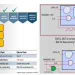
The above picture shows, how power saving can be done at the RTL level by setting the clock to be active only when required; such types of methods are meticulously utilized by the RTL Power Optimization tool, PowerArtist which is physical aware.


[Identifying connectivity failures, e.g. high resistance due to missing stacked via]

Totem can perform extensive checks on the layout to find any violation which can cause connectivity issues leading to electrical abnormalities.


[Power Integrity check, e.g. detecting worst instance not getting enough power]

Integrity of Power Delivery Network (PDN) has become important due to shrinking noise margin (as threshold voltage has remained constant, but supply voltage has decreased) and high performance requirement. In the above case, due to simultaneous switching of neighbouring instances, drawing maximum current through the same power grid, there is high voltage drop and hence the corresponding PDN needs adjustments.


[EM Analysis, e.g. detection of uneven current in a power line and its fix]

EM analysis takes care of Average, RMS and Peak current for both power and signal lines. Apache tools take into account all aspects of EM rules such as direction, temperature, topology, and VIA location.


[ESD Analysis with a case of failure due to ground connection during IP integration]

Excessive electrostatic discharge or electrical overstress (ESD) can cause device or interconnect failure. PathFinder can be used to find the root cause of ESD and fix.


[Substrate noise and its modelling to keep it under control]

As digital and analog circuitry sit on the same substrate, digital (aggressor) noise is injected into analog (victim) through the substrate coupling. A correct modelling of this noise injection must be done to keep it within limits. RedHawk and Totem use a smart extraction engine which can handle complex structures such as wide via arrays and metal structures.

Also, since a substantial portion of SoC is covered by various IPs, and they consume extensive power, their power integrity and reliability must be checked. Effect of various modes of operations of IPs at the top level must be validated. Totem can be used to analyze the layout down to transistor level.

Apache, in its Power Noise Reliability Platform has powerful tools such as PowerArtist for power analysis and fix at RTL level, RedHawk for system and full-chip level analysis and fix and Totem for AMS designs. These are high performance tools (with multi-threaded and multi-core architecture) which can handle large size flat designs of 100M+ transistors.

The webinar “Power Noise Reliability Sign-off of Custom Analog IPs” is worth going through; it provides good learning about today’s SoC issues and their solution.


Real Heroes Don’t Wear Capes!

Real Heroes Don’t Wear Capes!
by Daniel Nenni on 08-31-2013 at 6:30 pm


Real Heroes have many different jobs. My oldest son is a Math Teacher, he is a hero. You may have read about him before, he is the co-developer and administrator of SemiWiki. Think about it, without math where would the world be today?

My other son is a Fireman, Emergency Medical Technician, and also a hero. He is at the Rim Fire in Northern California near Yosemite. You may have read about it being that it is one of the most devastating fires in the history of California.

I would say the best advice I gave to my sons was to choose a profession that you have a passion for because you will be doing it for the rest of your life. Growing up in a military family with five brothers my goal was to make lots of money and that took me to computers which has been my life long passion. Now I hold a super computer in my hand packed with semiconductors that I helped make and it allows me to track my heroes every day.


Today there are about 5,000 Fire Personnel on the Rim Fire which has burned more than 200,000 acres (300+ square miles), destroyed dozens of structures, and threatened thousands more. My son fights fires with a chainsaw and a crew with rakes and shovels. They hike for miles and clear breaks. At night they light back fires trying to predict where the fire will go and head it off.


How did my son become a fireman? Interesting story, from high school he went to the fire science program at the local college. In the summers he was on the Davis Fire Crew training to do what he is doing today. After graduating with a fire science degree and an EMT certification he went to paramedic school. From there he went to various part time Fire/EMT jobs and finally to Cal Fire. I have never seen a kid work so hard following his passion. He trains tirelessly and has stacks of certifications. Sometimes we don’t see him for weeks at a time but thanks to semiconductors we are in contact almost daily.


You can monitor the Rim fire on InciWeb.org, the Incident Information System. Mandatory evacuation orders are still in effect. After two weeks containment is at 35% with an expected 100% containment date of September 20[SUP]th[/SUP]. Right now my son is protecting a city that is in the line of fire and the people there are very grateful! These people are very lucky to be surrounded by heroes at a time like this.

Rim Fire Fact Sheet

31 August 2013
Day 15

Acreage: 219,277

Largest fire in the United States to date in 2013·

No. 1-ranked on national firefighting priority list

Fifth largest fire in California history
·Second largest to date in 2013: Lime Hills Fire, Alaska 201,809 acres

States that have sent firefighters or other personnel:
41 and the District of Columbia

Cal Fire geographical units that have sent personnel
: 20 of 21

Uncontrolled fire edge:
107.4 miles

Completed containment line:
66.1 miles

Completed dozer line:
139.9 miles Proposed dozer line: 30.3 miles

Completed hand line
: 5 miles Road as completed line: 16.3 miles.

Acreage in Yosemite National Park
: 60,185

Proportion of the fire burning in Yosemite National Park:
27.5 percent

Size of the fire area:
Larger than the land area of San Francisco, Oakland and San Jose combined

Pounds of firefighter laundry washed:
10,534

Burned or damaged trees adjacent to power lines removed by Pacific Gas and Electric
:
4,929

lang: en_US


OTP Memory to Build Smarter Power Management

OTP Memory to Build Smarter Power Management
by Paul McLellan on 08-29-2013 at 11:20 pm

All chips have critical power management requirements, often with multiple supply voltages. Digital power management ICs (PMICs) are commonplace to convert unregulated voltages from batteries and noisy power supplies to fully regulated accurate power to keep even the most sensitive chips performing.

Powervation is a company that uses a multiprocessor SoC architecture for its digital power management solutions. The architecture comprises a proprietary dual core (DSP and RISC) processor, both RAM and Sidense one-time-programmable (OTP) memory, power conversion blocks, serial interfaces and more.


Powervation’s digital power management SoC products use two types of memory to perform the functions needed for their features and to provide for users. Firmware and DSP code, along with security codes and design and user-specific configuration parameters for the voltage regulator, are stored in Sidense 1T-OTP.

When the device is powered on, the contents of the OTP memory are loaded to a RAM for fast access to the processing unit. 1T-OTP provides long-term storage of vital code that determines power supply functionality, so it is crucial that this memory be reliable.

Sidense’s antifuse-based split-channel bit-cell architecture (1T-Fuse) in 1T-OTP minimizes bit-cell area (and its impact on total chip area) while allowing the memory to be fabricated in standard CMOS processes with no additional masks or process steps, and thus no extra processing cost. The single transistor architecture leads to very small size and the memories generate all the voltages needed both for programming and reading the memory, so no unusual power supplies are required. The antifuse technology is irreversible so that once programmed a bit cannot be “forgotten.”

Using Sidense OTM memories like this is much more cost effective than either putting other non-volatile memory technologies such as flash onto the chip, or alternatively using a separate off-chip memory or ROM. One chip is almost always a lot cheaper than two. For parameters that change occasionally, the Sidense technology can be used to create a pseudo few-time-programmable memory that Sidense calls emulated multi-time programmable (eMPT) operation. The registers are replicated a number of times and can be reprogrammed that many times, with the latest programming being picked up when the rmemory is read. For parameter memories that are typically small, this has negligible overhead especially when compared to other more expensive technologies such as flash.

The Sidense/Powervation white paper is here.


Semiconductor Market Back to Healthy Growth

Semiconductor Market Back to Healthy Growth
by Bill Jewell on 08-29-2013 at 9:00 pm

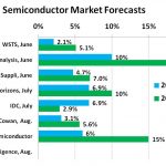
The worldwide semiconductor market is back to a healthy level of growth. WSTS data shows the 2Q 2013 global semiconductor market was up 6.0% from 1Q 2013 – the strongest quarter-to-quarter growth since 6.6% growth in 2Q 2011. Recent forecasts for 2013 market growth range from a conservative 2.1% from WSTS to an optimistic “up to 10%” from Objective Analysis. We at Semiconductor Intelligence are holding to our May number of 6.0% growth.

Forecasts for 2014 have a wide range – from IDC’s 2.9% (the only forecaster to show slower growth in 2014 than in 2013) to “over 20%” from Objective Analysis. We at Semiconductor Intelligence have increase our forecast for 2014 to 15% from our May forecast of 12%. The average for the 2014 forecasts shown is 9.4%, which is a strong growth rate for the semiconductor market considering the compound annual growth rate (CAGR) from the prior cycle peak in 2004 to the current cycle peak in 2010 was 5.8%.

How certain is the outlook for 2013? To reach 6% growth for the year, 3Q 2013 and 4Q 2013 quarter-to-quarter growth would need to average 6.4%. This growth rate seams very reasonable based on the 3Q 2013 versus 2Q 2013 revenue growth guidance from major semiconductor companies.

The midpoint of 3Q 2013 revenue guidance for most of the companies above is in the range of 3% to 6%. AMD projects 22% growth due to new products and design wins. Qualcomm expects flat revenue quarter-to-quarter based on the timing of key new product releases. ST Microelectronics’ outlook for a flat 3Q is blamed on its struggling wireless business. Excluding wireless, ST expects 3.5% growth. The upper end of guidance is in the upper single digit or double digit range for most of the companies. Samsung did not provide specific revenue guidance but expects 3Q demand growth for both DRAM and flash in its memory business and strong demand growth for image sensors in its LSI business. Micron Technology also did not provide specific guidance, but we estimated their growth based on their projections for DRAM and flash bit growth and price changes. The weighted average midpoint 3Q 2013 revenue growth for the above companies is 4.2% versus 3.7% growth in 2Q 2013. This compares to WSTS’ 6.0% 2Q 2013 market growth. Thus smaller semiconductor companies generally are experiencing stronger growth than the major companies listed above.

What will drive accelerating growth for the semiconductor market in 2014? Much of the growth will be driven by an improving global economy in 2014. The International Monetary Fund (IMF) July forecast called for global real GDP growth to increase from 3.1% in 2013 to 3.8% in 2014. Key drivers of the accelerated 2014 growth will be U.S. (growth accelerating from 1.7% in 2013 to 2.7% in 2014) and the Euro Area (recovering from a 0.6% decline in 2013 to 0.9% growth in 2014). China’s growth is expected to continue just below 8%. Although China’s growth is below the 10% plus rate of a few years ago, other emerging economies are showing accelerating growth in 2014 including Central and Eastern Europe, Russia, India, Latin America and southeast Asia.

lang: en_US


Foundry 2.0: Why It Is Different And Why You Should Care

Foundry 2.0: Why It Is Different And Why You Should Care
by Paul McLellan on 08-29-2013 at 5:22 pm

If you have been to an Ajit Manocha keynote recently, he talks a lot about Foundry 2.0. I covered his keynote at Semicon West in July here. Dan Hutcheson of VLSI Research interviewed Ajit about this new business model to identify it, see how it was different and see how GlobalFoundries were executing the model differently from the traditional model. The result is a video(21 minutes long) and a white paper.

The foundry business started with the sale of excess capacity in what we now call IDMs but back then we just called semiconductor companies. This was pure contract manufacturing. Since sometimes the company buying wafers might be a competitor of the company supplying them, this wasn’t a relationship based on trust and, since the excess capacity might go away, it was typically pretty short term too.

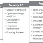
The true foundry business, with dedicated companies such as GlobalFoundries, started with the founding of TSMC. This was Foundry 1.0 and taking the business to the next level where it was a trusted partnership between the foundry and the fabless customers. This rode on the back of the fact that differentiation was moving from manufacturing to design and so owning your own fab was no longer a requirement for success. In fact, they were becoming so expensive that they were a liability. In addition to the cost of the fab itself, the cost of technology development for each process generation was also getting prohibitive. All of these made the foundry model attractive whereby the cost of the fab and process development would be amortized by the foundry across many fabless companies that specialized in design not manufacture. Eventually many IDMs joined the party, switching to fab-lite strategies, using foundry for their leading edge capacity.

In this era, deep technical access to the fabs was limited. Generally a foundry would release design rules and spice rules, and the design companies would run with them and create designs, tape them out and the foundries would manufacture them. Then a couple of things happened. Firstly, mobile (and consumer products in general) grew explosively and couldn’t tolerate a long product cycle. Design cycles needed to shrink and absolutely had to be right first time to hit their market window. And the processes got so complicated that some preliminary design and electrical rules were no longer enough to get working designs. And many designs increasingly consisted of 3rd party IP meaning that there were a lot of moving parts getting the first designs into a new fab/process: IP suppliers, EDA companies, fabless companies and, of course, the foundry itself.

The business model started to break down too, because the foundries wanted to sell fixed-price wafers (essentially making the designer responsible for yield) but the designers didn’t have the tools or the data to do that (and in their world would ideally just pay for good die, making the foundry responsible for the yield). The trust had broken down and the customer-foundry relationship started to be adversarial. Fabless companies saw what IDMs (especially Intel) could do and they wanted one of that too. They wanted a similar relationship to their foundries as a company like Intel’s design groups had with their manufacturing divisions.


This is Foundry 2.0. GlobalFoundries was well positioned having deep roots in an IDM (it was basically a spinout from AMD) and deep roots in foundry (once they acquired Charterered). Ajit himself had been a senior manager in an IDM, taken it through the transition to fab-lite and then fabless. The core of Foundry 2.0 is Collaborative Device Manufacturing, keeping the intimacy of the IDM internal relationships joined with the flexibility of the foundry-fabless model.

Foundry 2.0 has already seen significant success at GlobalFoundries. It is more like working with two internal departments as opposed to Foundry 1.0’s two companies focused too much on their own bottom lines.

VLSI Research white paper on Foundry 2.0, the Next Generation of Foundry-Fabless Relationships, Why It’s Different and Why You Should Care.

Video of interview by Dan Hutcheson with Ajit Manocha is here.


Imagination Has More Stuff Than You…Imagine

Imagination Has More Stuff Than You…Imagine
by Paul McLellan on 08-29-2013 at 1:04 pm

Imagination seems to be well known for a couple of things. Firstly, everyone knows that it is the graphics processor used in the iPhone and the iPad and lots of other phones. And they know that Imagination acquired MIPS at the start of this year.

But what people don’t seem to really appreciate is just what a huge portfolio of IP the company actually has and how successful they are: they actually ship over 3 million products per day, which works out at about 40 every second.


Imagination has processors in 4 main areas:

  • Multimedia: not just GPUs, but a new ray-tracing engine, video and vision processors. Remember about 75% of the internet bandwidth is video, and everything is going towards 4K pixels.
  • Communications: they call these RPU (for radio-processing unit) for connectivity, along with a lot of associated software for voice over IP etc
  • Processors: the MIPS product line, extended, along with operating systems, software stacks, debuggers and the like
  • Cloud: cloud back end processing to easily configure low-powered devices to offload complex processing. Enabling technology for the Internet of Things (IoT).

Yesterday, Imagination had the first annual executive/press event at the Stanford faculty club. Stanford university is especially appropriate since the MIPS architecture originated there.

John Hennessy, the original creator of the MIPS architecture along with his colleagues, gave a little of the early history. He tried to get existing computer companies interested in the MIPS architecture, perhaps the purest example of RISC architecture. But business conditions were not favorable. For example, IBM canceled their RISC processor, the 801 (as an aside, imagine how different the semiconductor industry might look if IBM had put that processor into the original PC instead of an Intel 8088). Gordon Bell told John that if he wanted to commercialize the processor then he’d have to found his own company. So, in 1988, he founded MIPS Computer Systems.

Silicon Graphics made extensive use of it and when MIPS was struggling they acquired it. Eventually in 1998 SGI spun MIPS back out again (now as MIPS Technologies) and then at the end of last year Imagination acquired them for $100M.

One problem MIPS had been having was uncertainty about its future. It is hard to get a semiconductor company to commit to a long-term use of your processor when it is unclear if the company is going to survive forever. It is funny say so today, but even ARM had that problem in the early days once the Newton was not a success and so their future was also uncertain. Now with Imagination, MIPS is doing well in the markets where it has traditionally been strong (communications, set-top-box and DVR etc). There are also green field opportunities like wearable computing. Imagination executives have a goal of 25% of the design wins in 5 years.


Of course they are the first to admit that the most difficult area is mobile, which is ARM’s stronghold. Imagination seems to think that the market wants a choice, as opposed to a monopoly. I’m not so sure myself. Firstly, there are some natural reasons for wanting to use a common architecture rather than lots of different ones in a given market. But also, while everyone might want more choices in principle, that doesn’t necessarily mean they want to act on that desire and license non-ARM core for a mobile device just to level the playing field for the good of the industry. Also, although Intel are not in the processor licensing business, ARM (and MIPS too, of course) are very aware of its push to leverage its process technology into a strong position in mobile. But the bottom line is that MIPS is in a much stronger position as part of Imagination than it was on its own.

Another thing I hadn’t realized is that Imagination had been working on their own internal general purpose CPU development before they acquired MIPS. In fact they had almost as many processor engineers working on it as MIPS had themselves. These engineers have now all been redirected to the MIPS line with the Warrior line the first MIPS processors since the acquisition coming later this year.

Details of the entire Imagination/MIPS product line is here.


It’s a 14nm photomask, what could possibly go wrong?

It’s a 14nm photomask, what could possibly go wrong?
by Don Dingee on 08-27-2013 at 3:16 pm

Let’s start with the bottom line: in 14nm processes, errors which have typically been little more than noise with respect to photomask critical dimension (CD) control targets at larger process nodes are about to become very significant, even out of control if not accounted for.

Continue reading “It’s a 14nm photomask, what could possibly go wrong?”