BannerforSemiWiki 800x100 (2)

The (re)making of Arteris, 1-2-3

The (re)making of Arteris, 1-2-3
by Don Dingee on 03-06-2014 at 6:00 pm

Success in a business with extended design-in cycles may look easy. In reality, there is a delicate balance between many factors. Some come to mind immediately: developing and releasing a good product in the first place; winning and keeping the right customers, not too few or too many; balancing investment between support and R&D; and constantly evaluating the landscape for disruptive change and newer ideas.

The semiconductor intellectual property business can test the mettle of even seasoned industry veterans. After all, an IP vendor only makes one piece of a solution; success means helping a customer make something complete that ships in volume with the idea inside. The bulk of the credit often goes unrecognized by other potential customers because of NDAs and confidentiality.

There is perhaps no greater endorsement for a company and their technology than when a superpower swoops in and buys the rights to the mainline IP by acquiring all or part of the firm. When our SemiWiki staff last visited one of these cases at the end October, the burning question was: How does Arteris move forward with their business after selling key network-on-chip technology (but not other customer royalties, retaining sales/marketing rights) and most of their engineering intellectual capital to Qualcomm?

I’ll just say that Qualcomm can be very persuasive, and it was probably the tech version of the “offer they can’t refuse” sans firearms but including bags of cash. Both Eric Esteve and Paul McLellan previously analyzed the highlights of this rather unique transfer agreement. Each touched on the notion that Arteris would likely take the cash and reinvest, adding new engineering talent in moving forward with their NoC vision.

Eric – Qualcomm-Arteris deal: high cost of differentiation
Paul – Qualcomm and Arteris: The CEO Speaks

Talent, indeed. Arteris has reached into the well and come out with three prominent names from a cross-section of the industry, filling key leadership positions.

  • Craig Forrest joins as CTO, and we only need one line in his bio to understand his fit: “… he led and created the semiconductor design groups responsible for the Application Processors in the first three generations of [Apple]iPhone products.” (Daniel Payne recently shared background on the A4, A5, and A6.)
  • David Parry catches on as VP of Engineering, bringing three decades of experience from Solarflare Communications and SGI. His bio cites extensive experience in cache coherency, and we can infer he also brings in-depth understanding of issues like QoS and high-bandwidth network traffic.
  • Benoit de Lescure is an interesting find, coming over as Director of Applications Engineering, lifted from the arms of Sonics where he held product management and applications engineering roles. He also brings perspective into Europe, with background including time at Thomson.

You can read more about these individuals, and thoughts from Arteris CEO Charlie Janac, in the official press release.

Arteris Recruits World-Class Engineering Leadership Team

The old saying that comes to mind with any organizational press release like this is “the proof is in the pudding”. The big news will be the next-generation Arteris NoC release, and subsequent design wins. However, they have kept their first (public) post-transform commitment, reaching into the likes of Apple and their key competitor for new engineering leadership and ideas. I suspect it won’t be too long before the next steps are seen.

lang: en_US


How to meet 3Ps in 3D-ICs with sub-20nm Dies?

How to meet 3Ps in 3D-ICs with sub-20nm Dies?
by Pawan Fangaria on 03-06-2014 at 1:30 am

It feels to be at the top of semiconductor technology by having dies with high density of semiconductor design at sub-20nm technology node stacked together into a 3D-IC to form a complete SoC which can accommodate billions of gates. However there are multiple factors to be looked at in order to make that successful amid often conflicting goals of power, performance and price. 3D-IC architecture provides large integration possibilities that can help meeting power and performance goals; however DvD (Dynamic Voltage Drop) hotspots need to be managed well along with full chip-package level analysis. Again emerging technologies such as reduced supply voltage (sub-1V), DVFS (Dynamic Voltage and Frequency Scaling), MTCMOS (Multi-Threshold CMOS) and LDO (Low-dropout voltage regulator) are being used to meet stringent low power demand while trying to meet performance and reliability goals. Reduced supply voltage (that reduces noise margin) along with high density of functionality and high operating speed induces significant noise into the system and that initiates the need to accurately model power/ground noise in the system to determine right levels of operating speed and voltage.

I was impressed with Apache’sRedHawk-3DX solution which is apt at handling these issues at sub-20nm and provides a right platform for power integrity analysis and sign-off for 3D-ICs that may accommodate billions of gates and operate at clock speed beyond 3 GHz. In order to accurately model and simulate power/ground noise, complete extraction of on-chip as well as package and PCB parasitics is done with due consideration to TSVs (Through Silicon Vias), interposer and micro-bumps. APL (Apache Power Library), on-chip inductance modeling, support for multi-port broadband S-parameter package/PCB netlists and EM modeling in RedHawk-3DX advances the accuracy levels at sub-20nm nodes.

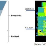
Accuracy and coverage of dynamic power analysis has been enhanced by the novel idea of ‘event’ and ‘state’ propagation techniques which utilize both, functional stimulus and statistical probabilities to determine the switching scenario in the design. RTL2Gates methodology is realized by utilizing a fast event propagation engine and RTL VCD at RTL level without requiring gate level vectors. Critical cycles with peak power are identified by using RPM (RTL Power Model) which equip the logic engine to determine the switching state of the complete design for cycle accurate DvD analysis. A state propagation engine uses toggle activity (at primary IOs, register outputs etc.) as input and a smart ‘detection and pruning’ technique to eliminate the traditional problem of underestimating toggle rates in the logic cone. The predicted toggle rates are used by RedHawk-3DX to perform time-domain VectorLess analysis. RedHawk-3DX also supports a mixed-mode, where part of the blocks use RTL or gate level VCD as available and rest of the blocks remain VectorLess to derive switching activity, thus enabling designers to perform accurate full-chip dynamic power noise simulation.

Since the PDN (Power Distribution Network) is shared across the chip or complete package, full-chip capacity along with package/PCB model inclusion is a must for accuracy of simulation results. RedHawk-3DX has ERV (Extraction Reuse View), a unique hierarchical extraction and modeling technology that delivers full-chip capacity and performance without sacrificing the sign-off accuracy. Additionally, techniques such as MPR (Mesh Pattern Recognition) and multi-threading are used to reduce physical memory and run-time.

LDOs can be seen in most SoCs as they provide more robust power supply to noise-sensitive parts of the design. However, model of a chip with LDO must capture all key operating behaviors of the LDO, including the change in its output supply voltage for different load current scenarios. The expanded low-power simulation capabilities of RedHawk-3DX enable creation and use of such models in full-chip power noise analysis.


[3D-IC Voltage Drop using Multi-Pane GUI]

Designers can analyze 3D/2.5D designs either in concurrent mode which simulates full layout details for all dies including interposer, or in model-based mode which uses CPM (Chip Power Model) to capture the electrical signature (current and parasitics) for some chips whose layout may not be available. Design architects can explore various design configurations for early prototyping of such complex structures. The multi-tab, multi-pane GUI provides great flexibility in analyzing multi-die designs by simultaneously projecting DvD hotspots and other results of multiple dies in various combinations.

RedHawk Explorer helps designers to qualify the input data, review design weaknesses, debug specific hotspots and provide feedback for design improvements. It provides concise summary of various analysis results. With its powerful cross-probing capabilities designers can easily locate, isolate, understand and resolve various power integrity issues.

It’s interesting to see RedHawk’s comprehensive chip-package-system level analysis environment which can enable designers to do package-aware IC simulation as well as chip-aware package/PCB simulation. A detailed technical paper is available at Apache’s website here.

More Articles by Pawan Fangaria…..

lang: en_US


Calypto: the View From the Top

Calypto: the View From the Top
by Paul McLellan on 03-05-2014 at 10:37 pm

At DVCon today I talked to Sanjiv Kaul, the CEO of Calypto. Just as a reminder, Calypto have 3 products, SLEC (sequential logical equivalence checking, also called sequential formal verification), PowerPro (sequential RTL level power reduction) and Catapult High Level Synthesis (that they took over from Mentor in 2011 in a complicated deal involving stock, people, products and cash).

2013 was a good year for Calypto with record revenues, including Q4 being the best revenue quarter ever. They ended the year with lots of cash in the bank too, which is great for a startup. In a startup, as Gordon Bell used to say, “cash is more important than your mother.” 2014 is starting out well with lots of customer engagements in high-level synthesis. In the power area, the move to FinFETs makes dynamic power a bigger problem, and since everyone has already done the easy stuff, this drives PowerPro business. SLEC is a sort of complement to both products, basically checking that nothing screwed up. The company is over 100 people and they plan to grow headcount 15-20% in 2014.

I asked Sanjiv if they have access to the Oasys synthesis technology that Mentor acquired at the end of last year. He said they are discussing it. Mentor and Calypto are separate companies (although Mentor owns a controlling interest in Calypto I have heard) so nothing is automatic. But the attraction of using Calypto’s HLS along with Oasys’s very fast RTL synthesis offers the possibility of going straight from C to placed-gates. There is also some possible synergy in the power area. Since Sanjiv used to be on the board of Oasys and did some of their marketing he knows the technology well.

HLS (from Mentor) and PowerPro/SLEC (from the original Calypto) are roughly 50:50 in terms of business. PowerPro is growing the fastest since it is part of an established RTL methodology whereas HLS is a methodology change which always takes time. But all 3 product lines are growing. Sanjiv told me that they will have several announcements this year, mostly in the second half. The only hint I could get from him is that one is something to do with power.

This feels like the year that HLS is going to take off. I guess Cadence feel it too, having just acquired Forte. I happened to be in the press room earlier today and overheard part of a roundtable about HLS. Devadas Varma, now at Xilinx, and coincidentally the founder and initial CEO of Calypto (and who I worked with at Ambit) was one of the participants. He worked at AutoESL and they were acquired by Xilinx and that technology is now part of Xilinx’s Vivado suite (as is Oasys’s synthesis technology that Xilinx licensed). He pointed out that clock rates have peaked at about 3GHz. It is just not possible to go faster due to power. So to get more performance, more parallelism is required. The best tool for handling that is HLS since it can automatically parallelize as much as you want, unrolling loops, duplicating functional units and so on. That is driving use of HLS inside Xilinx.

Today, the sweet spot for HLS is video since it is very complicated, the standards change all the time, and people care more about throughput than the precise number of clock-cycles. Perfect for HLS to make tradeoffs and come up with excellent implementations. More and more of the blocks that differentiate an SoC are using HLS to get that differentiation since it is too hard without. As a result the RTL level designers are starting to adopt HLS. The results that HLS can produce have improved enormously in the last year or two, so if you looked at the technology a few years ago and decided it wasn’t quite ready yet then take another look.

Details on Calypto’s products are here.


More articles by Paul McLellan…


Automating PCB Timing Closure, Saving Up to 67%

Automating PCB Timing Closure, Saving Up to 67%
by Daniel Payne on 03-05-2014 at 10:10 am

The benefits of using EDA software is that it can automate a manual process, like PCB timing closure, saving you both time and engineering effort. This point was demonstrated today as Cadenceadded new timing-closure automation to their Allegroproduct family, calling it Allegro TimingVision. On Tuesday I spoke with Hemant Shah of Cadence by phone to learn more about timing closure of PCB designs.


PCB routing where each color shows different timing margins
Continue reading “Automating PCB Timing Closure, Saving Up to 67%”


450mm Delayed and Other SPIE News

450mm Delayed and Other SPIE News
by Scotten Jones on 03-04-2014 at 11:00 pm

Last week I attended the SPIE Advanced Technology Conference. There were a lot of interesting papers and as is always the case at these conferences, there was a lot of interesting things to learn from talking to other attendees on the conference floor.

The first interesting information from the conference floor was that 450mm is being pushed out. What I heard is that with low fab utilization and the empty fab 42 shell, Intel has pulled all of their resources off of 450mm. Intel was one of the key players pushing 450mm and the comments I heard were 450mm won’t be this decade with 2023 as the new introduction date for high volume manufacturing. Some equipment companies appear to be putting 450mm equipment development on hold.

I think it is fair to say the conference was generally negative on EUV:

TSMC presented a paper where they really called out ASML. TSMC showed a chart of roughly a decade of ASML source power roadmaps where each roadmap shows a huge increase in the source power in the near future, and yet the reality is that source power has come up very little. TSMC has also seen low uptime on the sources on the systems they have in house (~70%). TSMC has an NXE3100 and recently received a NXE3300. On the NXE3300 system they had a laser misalignment in the source and the CO2 laser that vaporizes the tin to make EUV light damaged other components requiring extensive repairs. The key issues with EUV at present are source power and reliability and mask defects, the lack of progress on source power is a huge issue.

SEMATECH presented a paper on what it will take to get to high numerical apertures for EUV systems. The current NXE3300 is a 0.33 NA system that can produce the 10nm Logic node with a single exposure. For the 7nm logic node further improvements should be able to maintain single exposure but at 5nm a significant improvement in NA is likely required. In the SEMATECH talks they reported that to get NA above 0.4 more mirrors are required in the optical path. EUV mirrors have non negligible absorbance of EUV light reducing throughput. Also the system may have to go to higher magnification with either smaller field sizes or the mask size will have to grow from the current 6” to 9” or 12”. Increasing mask size is a huge undertaking requiring retooling throughput the mask supply change.

There were many other papers on EUV with Shot noise and pellicles being other interesting topics but I thought these two really made clear the challenges of getting EUV into production and then scaling it further. EUV is already late enough that it will likely miss the 10nm logic node and so 7nm and 5nm performance really becomes a key.

Interestingly there seemed to be a lot of optimism that we can achieve the 10nm, 7nm and possibly 5nm nodes by combining multi patterning with other techniques. There were a lot of papers on novel multi patterning schemes and shrink technologies. New immersion systems discussed by ASML and Nikon are promising 250 wafers per hour reducing exposure costs. There is a lot of work being done on simplification of the schemes. There is also help from the design and process technology side with increasing use of gridded designs and 3D memory. In 2013 Samsung introduced a 3D NAND technology that achieved bits/cm2 density similar to 1x NAND using a roughly 50nm lithography technology. The ability to scale memory in third dimension is a kind of equivalent scaling technique that can continue “scaling” with less pressure on exposure systems.

The key on multi patterning with other techniques will be cost. Quadruple and even Octuple pattering with up to 5 and 9 cut masks respectively looks like very expensive solutions. My company is the world leader in semiconductor cost modeling and we are currently doing a lot of work evaluating the economics of the various options. As we get though our work on cost projections I will post some observations.

There were also a lot of papers on Self Directed Assembly, Nano Imprint, E beam and other alternative but generally these techniques strike me as a lot further away from volume manufacturing.

One last personal observation, this was my first time at Advanced Lithography. I was very surprised to learn you don’t get the proceedings until six week or more after the conference. At other conferences I attend you get the proceedings on a memory stick when you arrive. I find being able to read the papers before seeing them presented and then go back and check them again after seeing the paper key to understanding the content. At paper after paper I was furiously taking notes as the information flew by and only captured a fraction of it. If anyone from SPIE reads SemiWiki, this is in my opinion a huge issue with your conference.

lang: en_US


What I Didn’t Know about Electronic Design Automation

What I Didn’t Know about Electronic Design Automation
by Daniel Payne on 03-04-2014 at 7:36 pm

I started using internal EDA tools at Intel beginning in 1978 and have worked in the commercial EDA industry since 1986, so it was a delight to read a chapter about EDA in Nenni and McLellan’s newest book: Fabless – The Transformation of the Semiconductor Industry. Starting in the 1970’s the authors talk about EDA, Phase One and how painfully manual the whole process of designing an Integrated Circuit was. I’ll never forget working at Intel at the time and performing manual Design Rule Checks (DRC) on an IC layout, when I stopped to ask my manager, “Hey, what about using a software program to automate this tedious task?”


Continue reading “What I Didn’t Know about Electronic Design Automation”


Dr. Walden Rhines Vision on Semiconductor & India

Dr. Walden Rhines Vision on Semiconductor & India
by Pawan Fangaria on 03-04-2014 at 11:00 am

Last month India Electronics & Semiconductor Association (IESA) held its Vision Summit at Bangalore in which luminaries from across the semiconductor and electronics industry presented their views about the future of this industry and India’s progress. Dr. Walden C. Rhines, Chairman and CEO of Mentor Graphicspresented interesting facts and trends about the semiconductor industry in his keynote speech. Dr. Rhines, a great technologist, strategist and visionary, I admire, particularly talked about what makes India best suited to embrace the fabless opportunity in the overall semiconductor ecosystem. I’m moved by his insight into Indian semiconductor business dynamics, strengths, weaknesses and how he rightfully cites a sustainable opportunity for India to focus upon. So what are the trends? Which segment is gaining traction?


If we look at the semiconductor market, fabless semiconductor design segment is showing the highest growth rate (16% CAGR), 29% of total IC revenue at $78B in 2013. Among top 50 semiconductor companies, 13 are fabless, that includes Qualcomm, Broadcom, AMD and Nvidia at 4[SUP]th[/SUP], 11[SUP]th[/SUP], 13[SUP]th[/SUP] and 16[SUP]th[/SUP] rank respectively. Another interesting fact is that the fabless revenue is highly concentrated with the topmost company garnering 19% and top 5 companies
together making 48% of total fabless revenue.


Look at the rise of fabless semiconductor companies with start of the new millennium until 2008 and then moderation. As of today, according to GSA estimate, out of a total of 1284 semiconductor companies 1011 are fabless.


Semiconductor IP (SIP) business is another segment that is seeing consistent growth. Again in this market, revenue is highly concentrated with single topmost company (ARM) taking away the lion’s share at 34% and top 5 companies together (ARM, Synopsys, Rambus, Tessera and Imagination) making 73% of the total SIP revenue.Dr. Rhines also talks about rising tape-outs at leading edge technology nodes (28nm and below), however still there is a large opportunity at older technologies (65nm and above) with 43% of IC production. IoT (Internet of Things) was cited to be the catalyst for yet another transformation of semiconductor industry. While that takes time, it’s ripe opportunity for India to raise its stake in fabless design and SIP business where it is showing strength. While new fabless start-ups are declining in the west they are growing in India.


Let’s look at where India stands in the Fabless Universe. India is among the top 5 semiconductor design locations across the world with 18 of the top 20 U.S. semiconductor companies and 20 European companies having their R&D centers in India. Considering overall semiconductor & electronics, 1031 MNCs have their R&D centers in India. Look at the right side pie chart, a considerable 5.3% of SIP companies are headquartered in India. All this data shows that there is good potential for India to grow in fabless semiconductor business. Dr. Rhines cites an example of Qualcomm on how it started with R&D services and became a fabless powerhouse revolutionizing the wireless communications industry.It was interesting to note from Dr. Rhines slides about the statistics on how the top talent in India is churned through IIT (Indian Institute of Technology) JEE (Joint Entrance Examination). While that is definitely a benchmark in India, I would like to add, there are some other excellent and effective regional engineering colleges in India; there are examples of professionals from some of these colleges who have set examples on the world map.


Dr. Rhines goes further citing the young and creative workforce with rising experience levels that makes rapid economic gains for India. It’s among top 5 destinations for foreign investments. In 2012, India had $25.5B of FDI (Foreign Direct Investment).There were nice examples of business model innovations. He cited examples of foreign “flagged” Indian companies, e.g. Beceem Communications, Redpine Signals and HelloSoft which have their headquarters in U.S. and design centers in India with the teams working with system architects over virtual networks.


Dr. Rhines then talks about “out-of-the-box” architectural innovations and how Mentor’s Veloce2 was developed with collaboration between U.S. and India teams. Its virtual stimulus concept and test bench acceleration were conceived and developed in India. This is a nice example of users and tool developers collaborating in close proximity.The complete set of the keynote slides is posted on IESA website here. My personal opinion as a concluding remark is that India must avail this opportunity in fabless world. It’s okay to have a fab, but if there is still close to 45% of IC production in 65nm and above, it may be beneficial to remain fabless because, in my opinion (I may be proved wrong) older fabs can slash fees much faster than gain in ROI on new fab. Of course, one needs to keep advancing towards leading edge technologies.

More Articles by Pawan Fangaria…..

lang: en_US


Synopsys Announces Verification Compiler

Synopsys Announces Verification Compiler
by Paul McLellan on 03-04-2014 at 8:00 am

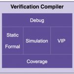
Integration is often an underrated attribute of good tools, compared to raw performance and technology. But these days integration is differentiation (try telling that to your calculus teacher). Today at DVCon Synopsys announced Verification Compiler which integrates pretty much all of Synopsys’s verification technologies (including the technology acquired in the SpringSoft acquisition) into a single tool. Verification Compiler is a complete portfolio of integrated, next-generation verification technologies that include advanced debug, static and formal verification, simulation, verification IP and coverage closure. Together these technologies offer a 5X performance improvement and a substantial increase in debug efficiency, enabling SoC design and verification teams to create a complete functional verification flow with a single product.


Existing methodologies using disparate tools are not very efficient, involving, as they do, duplicate steps, incompatible databases, multiple debug environments, inconsistent coverage metrics which all impact ease-of-use and productivity. And not in a good way.

Verification compiler ties together the big pieces of verification: static and formal verification, simulation, VIP, debug and coverage. The goal is to “shift left” and find more problems earlier in the design cycle and achieve coverage goals earlier.

Under the hood there is a huge amount of raw technology in the various engines, and then the uniform way of accessing it, debugging it and sharing data means that it is easy to use and the performance of the engines is not lost in translation and other inefficiencies. Verification Compiler really is a single product with native interfaces and consistent databases.

There is more than just integration of existing Synopsys technology. Probably the biggest new raw technology is that the formal analysis has been completely rebuilt from scratch with a lot more power, more performance and more capacity, an increase of 3-5X with full support for low power and clock domains.

There are big changes in debug too, focused on the challenges of large SoC development which has a large software component: interactive testbench debug, transaction debug, accelerated time to waveform for Zebu, AMS debug, power-aware debug, HW/SW debug. All with a common user-interface, way of displaying waveforms etc.

So how big a difference does this all make? Overall, a 5X performance increase (of course it is design dependent, ymmv, in some cases much more, occasionally less).

  • 3-5X improvement on static and formal verification
  • 4X on constraint runtime during simulation
  • 10X+ compile turnaround time with partition compile
  • 2X native power simulation
  • 2X faster verification IP
  • 2X with native FSDB
  • 4X with native Siloti

In addition to raw performance increase, Synopsys and their early partners reckon an increase of 3X in productivity due to concurrent verification, automated setup, and integrated flows and methodology. The concurrent verification methodology is supported by the licensing approach Synopsys have taken. One Verification Compiler license actually gives you three keys so you (or your team) can concurrently run static/formal, simulation, and debug. All from a single license key. The component parts are also available for separate licensing (so you can still, for example, have lots of VCS licenses for regressions).


So in summary:

  • Next-generation verification technologies, including static and formal verification, provide 5X performance improvement
  • Native integration of simulation, static and formal verification, VIP) debug, and coverage technologies into a single product boosts performance and productivity
  • New advanced SoC debug capabilities built on the easy-to-use Verdi[SUP]3[/SUP] debug platform enhance debug efficiency
  • Complete low power verification with native low power simulation, X-propagation simulation, next generation low power static checking and low power formal verification
  • A broad portfolio of VIP AMBA, Ethernet, MIPI, PCIe and more, integrated with simulation and debug for highest performance and productivity
  • Concurrent verification licensing enables 3X productivity improvement overall

Verification Compiler is in limited customer availability and will be in full release in Q4.

Much more detail on the Synopsys website here.


More articles by Paul McLellan…


Does Multiprotocol-PHY IP really boost TTM?

Does Multiprotocol-PHY IP really boost TTM?
by Eric Esteve on 03-04-2014 at 4:33 am

I have often written in Semiwiki about high speed PHY IP supporting Interface protocols (see for example this blog), the SoC cornerstone, almost as crucial as CPU, GPU or SDRAM Memory Controller. When you architect a SoC, you first select CPU(s) and/or GPU(s) to support the system basic functionality (Processor for Mobile application, Networking, Set-Top-Box etc.), then you define the various protocols to be supported by this SoC to interface with the functional system and the outside world. For an enterprise system, you will have to select one or several protocols among Ethernet (10G KR & KR4, 40G or 100G), PCI Express 3.0/2.1/1.1, SATA 6G/3G/1.5G or OIF CEI-6G and CEI-11G, to name a few. If you have read this previous blog (or if you have been exposed to high speed PHY utilization), you know that a 12 Gbps PHY IP design is complex, resource intensive and time consuming, as it may sometimes require several Silicon Test Chip before being 100% functional.

Chip makers have to face another challenge. As the cost of IC design rapidly increases due to the reduction in feature sizes, companies are no longer designing products that target just a single application. The SoC design must be architected to utilize multi-protocol physical layer (PHY) IP which can be connected to multiple different protocol controllers/MACs. Here comes the multi-protocol PHY concept. We may have to take a look at the picture below before going further:

The Physical layer is made of two sub-functions, the Physical Media Attachment (PMA), essentially analog and hard-wired, and the Physical Coding Sub-layer (PCS), digital and soft coded. If you architecture the physical layer in such a way that the PMA can be common to various (say N) interface protocols, and mux N protocol specific PCS, you can optimize analog design resources and cost, and certainly accelerate schedule when comparing with the design of N completely different PHY (except if you have an infinite source of analog designers, but does it really happen in any company)?

We can see the benefit in term of cost and schedule for the PHY IP vendor, but does it also imply a benefit for the chip maker, IP vendor’s customer? When this chip maker is targeting multiple applications, and need to optimize cost, designing only one SoC (or one SoC platform) which can be configured to address these various segments, integrating a single, multi-protocol PHY will certainly improve this IP “cost of ownership”. The PHY integration into the SoC workload will be minimized (one PHY IP instead of N PHY IP). The PHY qualification, using expensive lab hardware, and probably validation boards, will be simplified. Nevertheless, the two most important benefit will be NRE expenses improvement (divided by N in theory), and even more important, better time-To-Market (TTM). In fact, the chip maker benefit from the same TTM improvement than the PHY IP vendor! In the real world, designing and validating a multi-protocol PHY IP takes probably longer than for a single protocol… but the diversity of protocols is such that no IP vendor could bring to the market these N protocol specific PHY as quickly as this multi-protocol PHY.

Does a multi-protocol PHY IP improve TTM for Enterprise SoC chip makers? Certainly yes…providing that this PHY IP supports the protocols you need for your SoC interfaces. Let’s take a look at the protocol list supported by Synopsys’ 12G PHY:

  • IEEE 802.3 10G and 40G backplane (XAUI, KR & KR4), port side 40G, 100G (CR4 & CR10), and 10G (XFI, SFF-8431/SFI)
  • IEEE 802.3az Electrical Energy Efficient
  • SGMII, and QSGMII
  • PCI-SIG PCI Express (PCIe) 3.0/2.1/1.1
  • SATA 6G/3G/1.5G (Rev 3.2)
  • OIF CEI-6G and CEI-11G
  • CPRI, OBSAI, JESD204B

This multi-protocol PHY targets the SoC Enterprise market, and most of the relevant protocols are supported. We have not mentioned the PHY specific, complexes features, up-to-date PHY design techniques, like CTLE and DFE, PRBS or in-situ testing:

  • Multi-featured (CTLE and DFE) receiver and transmitter equalization: adaptive equalizers have many different settings, and in order to select the right one there needs to be some measure of how well a particular equalization setting works. The result will be to improve Rx jitter tolerance, ease board layout design, and improve immunity to interferences.
  • Mapping the signal eye and output the signal statistics via the shown JTAG interface: this allows for simple inspection of the actual signal. This in-situ testing method can replace very expensive test equipment (when a simple idea gives the best results!)
  • The pseudo-random bit sequencer (PRBS) generator send patterns to verify the transmit serializer, output driver, and receiver circuitry through internal and external loopbacks (keep in mind that Wafer level Test equipment are limited in frequency range, such a circuitry allows running test at functional speed on a standard testers).

If you are interested by Eye diagram measurement, and more specifically want to know how to reduce PCI Express 3 “fuzz” with multi-tap filters, you definitely should read this blog from Navraj Nandra (Marketing Director PHY & Analog IP with Synopsys). The very didactical article explains how adaptive equalization works, Inter Symbol Interferences (ISI), as well as help to understand how signals contain different frequency content, illustrated by four examples of forty bit data patterns. Navraj has been able to explain advanced signal processing concepts by using simple words, and this is everything but simple to do!

From Eric Esteve from IPNEST

More Articles by Eric Esteve…..

lang: en_US


ARM Lab in a Box

ARM Lab in a Box
by Paul McLellan on 03-02-2014 at 5:57 pm

St. Francis Xavier said “Give me the child until he is seven and I’ll give you the man.” ARM is not going for them quite that young but this week they announced their “lab in a box” for participating universities worldwide. It is actually a joint launch between the ARM University Program (which is not new) and various partners. Since ARM doesn’t actually make any silicon themselves, they can’t supply everything needed themselves even if they wanted to.

So what is in the “lab in a box” (LiB)?

The LiB package includes hardware boards from ARM partners, software licenses from ARM, and complete teaching materials ready to be immediately deployed in classes. Current partners supplying hardware boards include Freescale and NXP. The full contents of the box are as follows:

  • 10 x ARM-based development boards
  • 100 x ARM Keil MDK-ARM Pro 1-year, renewable software tools licenses
  • A complete suite of teaching materials from ARM, including lecture note slides, demonstration codes, lab manuals and projects with solutions in source.

Not surprisingly, Cambridge University is one of the first participants to get a LiB package. After all they are only a couple of mile away from ARM HQ and many of the founders of ARM graduated from the Cambridge Computer Laboratory (as did I). So you might expect that it would be the Computer Laboratory that loves the LiB. But the quote in the press release comes from Dr. Boris Adryan who appears to be in the department of genetics. He said:We were delighted to be one of the first institutions to receive the ARM University Program’s Lab-in-a-Box on Embedded Systems. It has immediately proven itself to me as an excellent resource for our research and teaching activities. The ARM-based materials it contains are helping us to connect our teaching of systems biology with the world’s latest embedded computing and sensing technology.

On April 14th and 15th, Xilinx and ARM are hosting two one-day workshops specifically for training faculty and researchers on the ARM SoC Lab-in-Box. The LiB is based on the ARM Cortex-M0 DesignStart processor core and Xilinx Vivado Design Tools. The one day workshop comprises lectures, hands-on exercises, and opportunities to network with experts from ARM and Xilinx. Details, including a link for registration, are here.

If you are not a “participating university” there are other ways to learn about ARM, program one, build applications and so forth. Probably the most accessible today is Raspberry Pi. This is a credit-card sized computer. It went on sale almost exactly 2 years ago (on February 29th so it is hard to say “two years ago today” this year) and sold 100,000 units on the first day. Since then over 2.5 million units have shipped.

The idea behind a tiny and cheap computer for kids came in 2006, when Eben Upton, Rob Mullins, Jack Lang and Alan Mycroft, based at the University of Cambridge’s Computer Laboratory, became concerned about the year-on-year decline in the numbers and skills levels of the A Level students applying to read Computer Science. There isn’t much any small group of people can do to address problems like an inadequate school curriculum or the end of a financial bubble. From 2006 to 2008, they designed several versions of what has now become the Raspberry Pi. The project started to look very realisable. Eben (now a chip architect at Broadcom), Rob, Jack and Alan, teamed up with Pete Lomas, MD of hardware design and manufacture company Norcott Technologies, and David Braben, co-author of the seminal BBC Micro game Elite, to form the Raspberry Pi Foundation to make it a reality. Three years later, the Raspberry Pi Model B entered mass production and within a year it had sold over one million units.

Buy a Raspberry Pi on Amazon (eligible for Prime) without ethernet hereor with here. $29.99 or $39.99 respectively.

Details of the Lab in a Box announcement here.

But wait, there’s more. At Embedded World in Nuremburg last week, Freescale announced the smallest ARM ever. Yes, that is a golf ball. It is a 1.6mm by 2mm package using wafer-level chip-scale packaging. Internet-of-things-ready.


More articles by Paul McLellan…