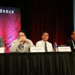
Bronco Webinar 800x100 1

System-Level Power Estimation

System-Level Power Estimation
by Bernard Murphy on 05-09-2017 at 7:00 am

When I first saw that Rob Knoth (Product Director at Cadence) had proposed this topic as a subject for a blog, my reaction was “well, how accurate can that be?” I’ve been around the power business for a while, so I should know better. It’s interesting that I jumped straight to that one metric for QoR; I suspect many others will do the same. I guess none of us is as objective as we like to think we are.


Here’s why. It is generally agreed that power estimation at the (implementation) gate-level can get within 5% of power measured on silicon – with caveats, but let’s use that as a working number. This has great value, but it’s primarily signoff value. If estimates are outside expectations, gate-level analysis won’t provide much help on where to make fixes. That’s why power estimation at RTL has become popular. Absolute accuracy tends to fall within 15% of gate-level which may seem less appealing, but relative accuracy (design rev A is better than design rev B) is better, micro-architecture experiments (clock-gating, power-gating, etc) can be performed quickly using the estimates as a metric, and significant power savings can be found at this level – much larger than anything possible at implementation. Point being, if you move up a level of abstraction, accuracy drops but payback jumps significantly and you can iterate much more quickly on experiments.

The same reasoning applies when you move up to the system (in this case System-C) level since, as is well known, power-saving techniques have increasing impact as you move up the stack from implementation to application software. In this case, at RTL you can tune micro-architecture, at System-C you can tune architecture, with a bigger potential payback.

Of course, that only helps if you are able to optimize the design at the system level. System-C is still on the fringes of “traditional” designer consciousness in the Bay Area though that is starting to change with the rise of design in system houses and it remains popular in Europe and Asia, especially where there maybe isn’t so much legacy investment in RTL methodologies and training. Some groups in the larger semiconductor companies are also getting in on the action. You too might start to understand the appeal as you read the rest of this blog.

The bulk of this system power estimation flow is based on RTL power-estimation, using Palladium or Incisive/Xcelium as the activity-modeling workhorse and Joules as the power-estimation engine. That answers one part of the accuracy question – in principle this flow should be as accurate as an RTL estimation flow, as long as you don’t mess with the generated RTL (if you do mess with the RTL, you can always re-run power estimation on that RTL). Not messing with the RTL (taking HLS output direct to implementation) seems to be a trend among designers using System-C, suggesting accuracy for this flow should be close to RTL accuracy.


Cadence illustrate use of this flow using design of a 2-dimensional IDCT for which they want to explore various architectural options. In this flow, they’re using Stratus to synthesize System-C and flow automation starts from this point using Tcl scripts which also build the appropriate Makefiles to drive simulation or emulation and power estimation as needed.


Where this gets impressive is the range of options they were able to explore. They looked at 84 different architecture options covering differing word-widths, trading-off sharing versus parallelism, storage as memory versus flip-flops and multiple other options. This analysis was automated through scripting from Stratus, so once setup, they just pushed the button, sat back and watched the results roll in. The setup takes work, but once in place it becomes relatively easy to extend analysis to cover more options.


At that point, it’s trivial to pick off best architecture options. Looking at performance, energy and area, they found that best architecture can vary quite significantly as these targets change. Perhaps unsurprising, but getting from a hand-waving observation to figuring out the optimum architecture for a target application is going to be a lot of work unless you can use a flow like this.

That was an internal experiment, however Cadence also cited a real case study for a satellite application where an existing C/C++ implementation on a DSP had to be migrated to RTL. Previous attempts were based on hand-developed RTL, starting from the C/C++ code. Switching over to the System-C approach, the design team was able to get to first RTL in 1 week and an optimized design in 5 weeks, exploring multiple architectural options. Area was 28% smaller and power was 4X lower than for the hand-coded version. Purely through optimizing the architecture. As easy Moore’s law cost/performance gains evaporate, it makes you wonder how much architectural wiggle room may be untapped in other designs. And whether this might be a motivator to migrate more block design to System-C. Food for thought.

You can read a more detailed paper on the internal experiments HERE.


We Need Libraries – Lots of Libraries

We Need Libraries – Lots of Libraries
by Tom Simon on 05-08-2017 at 12:00 pm

It was inevitable that machine learning (ML) would come to EDA. In fact, it has already been here a while in Solido’s variation tools. Now it has found an even more compelling application – library characterization. Just as ML has radically transformed other computational arenas; it looks like it will be extremely disruptive here as well.

By now we are all familiar with machine learning as it is used in recognition applications. Rather than writing hard coded software to recognize a specific object, like a stop sign, thousands of examples of stop signs (and not stop signs) are given to a machine learning training application. The output of this training is a data set that can be used by the recognition engine to identify a stop sign, or whatever object the training was done with. The beauty of it is that no object specific code needs to be written. Next time the same ML software can be trained and used for recognizing pedestrians, other cars, faces, or just about anything. Interestingly these algorithms are now performing better than humans at picking a face out of a crowd.

So, what about library characterization? Well instead of recognition, it relies on ML’s ability to create response surface models. These are used for simulating complex multivariable systems. Conceptually it works the same way as recognition. When it is given a ‘sparse’ data set, it can extrapolate with extremely high accuracy to provide results across the full spectrum. Much the same as how ML can recognize a face in the rain on a grainy image with low light – a situation it had not encountered before. Oh, and in case I forgot to mention it, ML does this fast.

Moving to the library problem, the ‘sparse’ data comes from representative cells, one for each family of cells. Then for this reduced set of cells, Solido’s ML Characterizer automatically selects what are called anchor corners. These are where there are distinctive features in the response surface. The anchor corners of the representative cells are used as training data to create a complete response surface model. With the response surfaces in hand the ML software can predict cell performance to produce new libraries over a wide range of processes, voltages, temperatures, back biases, etc. Oh, and in case I forgot to mention it, ML does this fast.

One example Solido discusses is for a library of 475 cells. To obtain 61 PVTB corners at one threshold, they started by running 36 of the corners with Liberate. The remaining 25 corners were produced with Solido’s ML Characterizer. It only required 3 hours and 20 minutes, running on 50 CPU’s to compete this task. More time could have been saved by pruning the cells that were used for training.

To ensure library quality, comparisons have been made with traditional characterization and the results differ by low single digit percentages. This puts it in the same league as the level of correlation one would look for in comparing SPICE simulators. Solido also offers a method of adjusting the tilt on the error so it is biased toward being pessimistic, if desired, to prevent optimistic results from interfering with yield later on.

The other component of the Solido ML Characterization Suite is their Statistical Characterizer which is used for producing Monte Carlo accurate statistical timing models. It can produce SPICE accurate models on the order of 1000 times faster than brute force. Its output includes AOCV, LVF and POCV values, and works well with non-Gaussian distributions (none of us live in an ideal world after all really).

Waiting for updated libraries when new PDK’s are released by the foundry can add lengthy delays to projects on new process nodes. Alternatively, design teams can discover late in the development process that libraries for a critical process corner are not available. Waiting for new libraries can be excruciating and expensive – especially if tapeouts are delayed. Finally, having run STA on a few additional corners can bring a great deal of peace of mind.

After learning about the ML Characterization Suite from Solido, I thought about the scene in the original Matrix move when they needed weapons before going back into the Matrix. They were standing in the empty “construct” and then racks of endless numbers of weapons appeared out of nowhere for them to use. While perhaps not quite with such a dramatic flair, ML Characterization will forever profoundly change how libraries are created and used for design projects. Solido has more information about their ML Characterization Suite on their website.


Noise, The Need for Speed, and Machine Learning

Noise, The Need for Speed, and Machine Learning
by Riko Radojcic on 05-08-2017 at 7:00 am

Technology trends make the concerns with electronic noise a primary constraint that impacts many mainstream products, driving the need for “Design-for-Noise” practices. That is, scaling, and the associated reduction in the device operating voltage and current, in effect magnifies the relative importance of non-scalable phenomena, such as noise. This makes what used to be a second order variable that was important only for specialty applications, into a primary concern, affecting most of mainstream type of designs. Thus for example, Flicker Noise and Random Telegraph Noise are major components of the overall variability budget in modern CMOS devices, and ultimately have direct impact on SRAM bit cell yield, DAC/ADC least significant bit resolution, clock jitter, etc.. The background of the noise phenomena and the relevant technology trends is outlined in recent Design-for-Noisepaper.In the past, the industry tended to evolve a set of methodologies and practices to manage new phenomena in technology – such as for example the Design-for-Manufacturability (DfM) practices for sub-wavelength lithography, or Design-for-Reliability (DfR) practices for managing the various intrinsic failure mechanisms (Electromigration, hot carriers, TDDB, NBTI, etc..). Hence “Design-for-Noise” (DfN) is a term used to describe the new practices necessary to manage the effect of electronic noise in advanced technologies.
The DfN methodology focuses on implementation of new solutions in test and characterization arena, that can then be used to ensure that the design is robust and the manufacturing process is stable with respect to the noise phenomena. This approach is analogous to the case of the DFM solutions, that ended up in implementation of OPC and RET practices in the process end of the product realization flow, rather than directly changing the design methodologies, per se. That is, rather than developing radical new designs and associated methodologies, it is believed that a practical approach for managing noise in advanced IC’s is to enhance the well-established SPICE-based simulation methodologies with better noise characterization, better noise models and better noise process control practices.

Thus, instrumentation and methodologies that enable direct (rather than inferred) measurement of noise is essential for realistic and practical DfN. The measurement technology must be accurate enough to resolve the minute noise signals (~fA’s), fast enough to generate statistically valid data needed for corner and/or statistical noise models (~sec’s per bias point), and simple enough to be incorporated in standard WAT test; all within the usual lab and test floor throughput and cost constraints. Such measurement technology then enables accurate SPICE simulation for noise, and ensures process control and consistency, both of which are necessary to define and manage suitable margin for noise phenomena – all within the reasonable economic constraints.

These seemingly conflicting constraints – accurate AND fast, economical AND addressing complex noise characterization – can be realized using state of the art measurement hardware integrated with advanced Artificial Intelligence software.

Test hardware capable of resolving fA noise signals normally requires long measurement time, necessary to ensure that all transients have settled and to enable averaging the signal over many thousands of data points. Hence noise characterization requiring minutes per bias point per DUT is not unusual. This kind of test time has therefore traditionally restricted direct noise characterization to engineering device characterization lab, and is normally performed only occasionally, early in the technology life, as a part of extracting and calibrating device models. Note that a corollary of this characterization approach, dictated by prudent engineering practices, is to bias the noise models on a very conservative side, to ensure adequate margin for any process variability.

However, use of advanced machine learning algorithms, along with the suitable training procedures, in conjunction with state of the art hardware, enable a drastic acceleration of data acquisition without compromising of accuracy. This can result in up to an order of magnitude reduction of the overall noise test time. This type of acceleration then enables not only noise characterization over a statistically valid sample size necessary for extraction of corner models, but also allows implementation of direct noise measurement in production process control environment. Note that since noise is not correlated with any of the standard process control metrics (IDsat, IDlin, Vth…), direct measurement is the only way of tracking the impact of process variability and process optimization on actual device and circuit noise.

Thus, use of machine learning enables a drastic acceleration of noise test time, thereby making noise characterization a practical direct process control metric, even within the typical volume manufacturing throughput and economic constraints. This in turn, enables development of statistically valid noise models to allow designers to optimize the noise margin with confidence, and process control practices to ensure consistent IC product yield and performance throughout technology ramp. Design for Noise at its best !!!
Platform-DA, a Process-Design Integration Infrastructure company with deep knowledge of device characterization and modeling, has applied its proprietary Artificial Intelligence algorithms to develop an advanced noise characterization solution. It provides a complete and integrated noise solution, combining state of the art measurement hardware, proprietary data acquisition and management algorithms, and device and noise modeling software.

The hardware includes not only the SMU’s but all the necessary cabling, jigs and even a probing solution, enabling easy integration with any test environment. The software encompasses not only the machine learning based data acquisition control, but also user friendly data management and visualization tools. And the model extraction environment includes not only the model extraction but a complete set of in-situ QA tools, resulting in accurate device models compatible with all the standard SPICE simulators.

You can read more about PDA on SemiWikiHERE. PDA will be participating in DAC 2017 in Austin, and will be demonstrating these capabilities.


Dear Cadence: Calibre Didn’t Run Any Dracula Decks

Dear Cadence: Calibre Didn’t Run Any Dracula Decks
by Mitch Heins on 05-04-2017 at 2:00 pm

After reading the Cadence blog post –Dracula, Vampire, Assura, PVS: A Brief History” – Dr. Andrew Moore has written the below article where he helps readers get a sense as to what “the year of hell” was like, from one of the key individuals who lived it. Andrew also addresses and corrects some of the “urban legends” on how Calibre came out on top. Sorry, no pictures other than this one of Andrew currently working at NASA. None the less, this is anexcellent read!

Dear Cadence: Calibre Didn’t Run Any Dracula Decks
It was refreshing to read “Dracula, Vampire, Assura, PVS: A Brief History,” as it frankly outlines the technology missteps and sales myopia that have made Cadence’s design rule checker products irrelevant since the 0.35-micron design node. However, it neglects to mention a couple of important academic antecedents, misstates the evolution of DRC languages, and greatly understates the magnitude of sweat and toil required from application engineers during “the year of hell” to help designers unshackle themselves from the limitations of Dracula’s command set. Its glib statement that Calibre “would run any Dracula deck” is simply wrong.

Software version instability created a problem for chip designers, and Cadence’s Dracula solved it – for a price. Even though Dracula was not free, it was a welcome alternative to free academic design rule checkers (for example, Magic from UC Berkeley, and runDRC from Caltech). Source code control was still in its infancy in the 1990s, and academic tools changed by the semester, often with no archived version history. How can you risk signing off a chip with a version of a software program that runs differently than the version, no longer available, that you used when you designed the chip’s individual parts? Hundreds of design teams purchased a perpetual license for a commercial tool, archived, maintained product – Dracula – to remove that risk, and the commercial DRC market was born.

In the era of 1.0- and 0.5-micron designs, semiconductor processing chemistry was rather coarse, and the design rules were simple. As etching, deposition, and implantation technologies became more precise to enable submicron silicon processing, design rules became more complex. This introduced a new risk: even the most up to date version of a DRC tool could be inaccurate if design rule checks written in its command language did not encompass all of the complexity of submicron rules. Different academic tools gave different DRC errors, which were different than the errors that Dracula found. Were these differences just false positives? Were there false negatives that none of the available tools were finding? Routinely, designers ran a DRC tool and then crawled over the entire design, manually verifying each violation that DRC uncovered and looking for other design rule violations that were not detected. A design crawl took hours of panning, zooming, inspection, and thinking. The lack of confidence introduced by complex submicron design rules and inadequate software DRC created more productivity problems than DRC software was solving.

This hybrid method (software DRC plus manual inspection) became untenable as layouts got bigger and bigger. Academic tools and Dracula simply did not have the capacity for large layout files. The designs were getting so large that manual traversal was taking more than a day. I kept a running tally of the size in megabytes of the biggest known GDS file from 1997 to 1999; when it exceeded one gigabyte in late 1999, I stopped keeping track. By then, manual inspection took more than two days, and all of the first generation DRC tools (Magic, runDRC, and Dracula) would run for a few hours and then crash on large 0.25-micron designs. Accuracy and capacity risks were foremost in the minds of product managers and tape-out engineers, who scrambled to find ways to cut the design into manageable pieces and verify them, in parallel, by teams of engineers.

Mentor and Avanti fielded products (Calibre and Hercules, respectively) to minimize these newly emerging accuracy and capacity risks. Calibre and Hercules had richer commands that allowed a clever designer to find all true errors and to sift through false positives, mitigating the accuracy risk. Both of these tools also took advantage of design repetition, so that multiple instances of the same block needed to be checked just once, except at their boundaries with other blocks of layout. This lowered the effective size of the design and sped up runtimes for most designs, mitigating capacity risk. As a former student of Carver Mead at Caltech, this was obvious to me, but for most designers it was a new paradigm. I spent a lot of time with designers manually looking at the boundaries of repeated blocks (e.g., bit cells, flip flops, pads, and shift registers) signing off and coding past false positives and making sure that there weren’t false negatives. They were relieved that it was possible to check the chip manually again, because they could be confident that it was not necessary to peruse large areas that were just arrays of identical parts. To be double sure, designers ran the first-generation tools on each of the repeated blocks to verify that they were individually error-free. After all, the “bit cell tools” were free (academic) or on a perpetual license (Dracula) that was already paid for.

Everybody knew that this was just a temporary reprieve, though. The manual inspection of array boundaries was getting more and more time consuming. Now product managers were pressuring designers to shorten the entire DRC sign-off to a few “spins,” with each spin made up of an overnight DRC run, followed by manual inspection of the results the next day. Ten spins (two five-day work weeks) were usually tolerated – if a company allowed more than ten spins, the product manager complained about slipping product release schedules, while if it insisted on fewer, the designer would not guarantee that the chip would actually work. Semiconductor executives did their homework, learned the funny names of the tools that were alternately creating and resolving this bottleneck, and gave their product teams a year or so to cut the time in half. They also added budget to purchase second-generation (hierarchical) DRC tooling and to hire new people to evaluate and use it.

Mentor and Avanti executives and account managers saw an opportunity to replace the first-generation DRC product, Dracula, with their respective second-generation product (Calibre and Hercules, respectively) and thereby harvest all of this newly allocated software budget. All that was needed was a little sweat and toil from their application engineers. I trained a lot of those application engineers, and worked side-by-side with them in what became known as “the year of hell,” which ran roughly from summer 1998 to summer 1999.

Designers insisted on running both Dracula and a second-generation tool on each chip layout, to have all possible awareness during this transition. Naturally, it occurred to everyone that it would be more efficient if the second-generation tool could read the Dracula rule set directly. DRC software architects were reluctant to implement this concept. For one, they argued, mapping a “flat” command set onto a hierarchical architecture was demonstrably silly. Secondly, they asked, “Do you really want to take on the liability of actually creating false positives and missing true positives, just to reproduce the inadequacies of a first generation tool?” Third, Cadence woke briefly from its slumber in 1999 and slightly expanded the Dracula command set, so that direct implementation became a moving target. There were other rebuttals that were more subtle, but by the strength of these three points, DRC software architects won the argument.

As a result, several standalone programs were composed (by designers, academics, and enterprising application engineers) to translate, as best as possible, Dracula commands to Calibre and/or Hercules commands. Dracula translator developers communicated by phone, email, and in ad-hoc meetings at design automation conferences to share ideas and code. These translators succeeded, at best, according to a set of 80/20 rules: translate 80% of the commands, or reduce run time by 80%, and let each individual chip design team take care of writing rules to address the other 20% on a case-by-case basis. These translators read in a Dracula rule file, written in Dracula’s command language, and output a Calibre or Hercules rule file comprised of Calibre or Hercules commands. The untranslatable 20% was ignored, output as comment lines, or as output as unreadable garbage text.

The problem, of course, was that if the translator ignored 20 percent of Dracula commands, and if the tape-out team did not somehow check the actual design rules corresponding to that 20%, the result was a dead chip, with short circuits, open circuits, intolerably high transistor contact resistance, etc. As a result, designers around the world spent a lot of their time (say, 80%) writing and testing Calibre commands that accurately checked the design rules, which were not checked properly by that 20% of the enfeebled Dracula command set. Design software company application engineers were called in to help during “the year of hell.” I was asked to help the newly emerging Asian foundries with the transition to second generation DRC that year, and I wrote a lot of Calibre rules on plane flights to Taiwan. There were dozens of foundry fabrication processes, and I saw that I was reusing manually written chunks of Calibre code to replace untranslatable, defunct Dracula code across several processes. To alleviate the burden on application engineers and to educate designers, I started capturing these chunks and a description of what they were checking in application notes. I have heard that the same thing happened for people trying to displace Dracula with Hercules across several semiconductor processes.

Calibre never read Dracula commands directly, because to do so would introduce the risk of incorrect chip signoff and because second-generation (hierarchical) DRC is fundamentally different from first-generation (flat) DRC. For the same reasons, it did not read Magic or runDRC commands either. The same is true today: Calibre only reads Calibre commands.

-END-

Bio: Andrew Moore earned a BSEE at the University of Illinois, Urbana, and a Ph.D. in Computation and Neural Systems at Caltech. Before joining NASA as a Research Aerospace Technologist in 2012, he served in several technology, sales, and executive roles in industry. These include two tours at Mentor Graphics (Calibre Technical Marketing Manager in the late 1990’s and PacRim Technical Director from 2009-2012), Deputy Director of Design Marketing at TSMC, and Vice President for North America and Europe at Luminescent.


Data Center Explosion Push for Fast Adoption of 25G

Data Center Explosion Push for Fast Adoption of 25G
by Eric Esteve on 05-04-2017 at 12:00 pm

The data center rack server market is estimated to growat a high Compound Annual Growth Rate (CAGR) of 20% to reach $90 billion by 2021. Such growth is due to the significantly rise in the number of connected devices, the growth in the volume of data per device and theneed for quick processing of high-volume data. Much of these data travels through an Ethernet port and this is the driver for the development of the 25G high-speed Ethernet standard and its associated standards.

Prior to the introduction of 25G Ethernet, manufacturers had to build 40G or 100G by using 10G lanes, 10 lanes of 10G to reach 100G. The introduction of the 25G lane speed provides a scalable path to 100G while achieving significantly improved bandwidth when compared to 40G Ethernet. The picture below is extracted from a report by Cisco and clearly shows the exponential nature of the volume of data growth.

I have frequently written about interface protocols, from PCI express or USB to MIPI, highlighting how important it is to manage the development of the physical layer (the PHY) based on aserializer/deserializer (SerDes). Just a reminder, the PHY layer is made of three logical parts, the PCS (Physical Coding Sublayer), the PMA (Physical Medium Attachment Sublayer) and the PMD (Physical Medium Dependent Sublayer).

For most of the protocols, the IP vendor will deliver the PHY up to the interface with the controller, including the PCS, the PMA and the PMD, and the MAC (Media Access Control Sublayer) will be integrated in the controller IP. Except for the Ethernet protocol! Instead of two components (PHY/PCS and Controller) the vendor(s) will market three blocks: the MAC, the PCS and the Ethernet PHY (including the famous SerDes). In fact, the vendor may decide to integrate the MAC and the PCS together, but the PHY will stay apart. The split for Ethernet IP is based on the nature of the design (analog or digital) more than on logical layers.

Synopsys propose the DesignWare Enterprise MAC, which can be easily integrated with the Synopsys PCS layer. This PCS IP is compliant with the IEEE 802.3 and consortium specifications for 1G, 10G, 25G, 40G, 50G and 100G Ethernet PCS layers. When using the 25G PHY, the PCS supports various interfaces including single 25G, 2x25G for 50G Ethernet, and 4x25G for 100G Ethernet. Some of the key optional modules include the Read Solomon Forward Error Correction block (RS-FEC), link training support, and auto-negotiation.

Based on the Consortium’s initial work, IEEE standards for 25G Ethernet are now defined in both single lane and 4 lanes of 25G. The Table below shows IEEE standards associated with 25G Ethernet with related electrical specifications.

The Enterprise MAC and PCS integrates seamlessly with the DesignWare Multi-Protocol 25G PHY IP. The configurable transmitter and receiver equalizers enable customers to control and optimize signal integrity and at-speed performance, and the continuous calibration and adaptation (CCA) provides robust performance across voltage and frequency variations. For data center applications, the signal integrity and the jitter performances have to be outstanding to comply with a very low bit error rate (BER) and the power should be kept as low as possible with support for Energy Efficient Ethernet (EEE).
The 25G Ethernet standard supports various hardware interfaces such as chip-to-chip, chip-to-module and backplane. Chip-to-chip and chip-to-module at 25G significantly improve the overall system performance, while backplane Ethernet supports the evolving blade server market specifically moving from 1G to 10G and now 25G.

The figure below shows how 25G Ethernet can be used to both drive interconnect between the different chips/modules as well as the connection for modules via passive or active cables at the port side. It also shows the various implementations of the 25G Ethernet standards: single lane 25G Ethernet, 2x25G for 50G Ethernet or a 4x25G for 100G Ethernet. This flexibility gives designers a powerful set of interfaces that can be used in applications ranging from the switch fabric, traffic managers, and as interconnect to other modules in the server.

The 25G Ethernet standard is the new standard for connectivity in the data centers. The specification allows for transmission of more data in less time, and supports multiple hardware interfaces to give designers flexibility in designing their SoCs for various high-end computing applications

This standard, initiated by the 25G/50G Consortium and now by the IEEE, is expanded to a robust set of published and approved standards as part of IEEE 802.3. You can find papers describing the 10G Ethernet standard written as early as in 1999 (by the IEEE 802.3 High Speed Study Group, June 1, 1999). There is no doubt that the next standard coming after 25G, or the 50G Ethernet, will be released far much faster than the time it took to move from 10G to 25G. The need for quick processing of high-volume data is still growing exponentially!
By Eric Esteve from IPnest

More about DesignWare Ethernet Solutions: Synopsys’ complete Ethernet 25G solution


Simulating ADAS

Simulating ADAS
by Bernard Murphy on 05-04-2017 at 7:00 am

Simulation is a broad technique spanning certainly digital logic and circuit simulation but also methods beyond these which are particularly relevant to ADAS design. In fact, much of the design of full ADAS systems begins and ends with these types of modeling. This is in part due to the need fully validate integrity and reliability of electronic systems all the way from the system level down to chip design and in part because sensors are as much a part of the system as the chips; for these sensors correct functioning / integrity / reliability depends as much or more on the surrounding environment and must be accurately modeled before it is built.


Ansys recently hosted a webinar highlighting several examples of this kind of modeling relevant to early-stage design and late-stage analysis for ADAS systems, in a range from electrical to electromagnetic, thermal and mechanical analysis. In fact, it is often necessary to combine two or more methods to get a realistic understanding of behavior, in an approach known as multi-physics analysis. While there are other multi-physics solution providers, as far as I can tell Ansys is the only one with a solution extending all the way from full-system structural, fluid dynamics and electromagnetics down into detailed chip and package analysis. (They also partner with TSMC on modeling for InFO systems, which should give you a sense of their technical depth in this multi-physics domains.)

The first half of the webinar discussed need to ensure integrity and reliability for subsystems (say a board) down to the design of the die in an SoC on that board. Functionality isn’t a primary consideration here, but thermal, power and signal integrity are, as are meeting EMI/EMC, ESD and mechanical objectives. This has become a bigger deal than you might imagine, pulling in multi-physics analysis across the range from chip to package to system.


The problem is that in ADAS (and some other cases) you can no longer decouple system design from chip/package design, thanks to several factors. There’s a lot more electronics in modern cars (as much as 40% of the value of the car), a lot more wired and wireless communication in the engine and cabin and those systems are aggressively power-managed because the value disappears if they drain the battery. All of that adds up to a lot more interference, a lot more heating and cross-system challenges in holding power rails steady between the board and the chip.


System components like sensors may switch (from a power consumption perspective) slower than an SoC, and impedances and therefore response times differ widely between board, package and system levels. So managing power and signal integrity requires careful design across these three levels. Of course, doing this also requires an understanding of thermal properties from chip to package to system. Which in turn also affects design for electromigration (EM) reliability at each level. And of course heating on the board can lead to warping, delamination and solder ball fracture so a mechanical analysis may be required. Similar considerations apply for EMI/EMC/ESD optimization.

It might seem that all this messiness could be avoided if the OEM/Tier1 just gave the chip/package design team a decent set of operating conditions/margins and let system and chip design decouple at that point. But it is becoming increasingly obvious that approach results in impractical over-design, failing to meet acceptable cost, performance and reliability goals. Co-design has become the only way to meet some of these objectives. Indeed, reliability alone, now demanding 15+ year lifetimes for critical components, has significantly contributed to these tightened expectations. That is driving increasing interest in the kind of multi-physics co-design, from chip to package to system, offered by Ansys.

The second half of the webinar focused on the sensor side of the design problem, in this case radar antennae. You can’t read anything about ADAS without seeing mention of radar, lidar and optical sensors for collision avoidance and autonomous control. Unfortunately, most such pieces don’t get past a mention, diving instead straight to chip-level architectures for recognition based on sensor output. But those antennae must be designed too and there’s a lot of interesting 3D electromagnetic simulation in that design. This section covered additional topics, including EM compliance, toll-booth pass-detection and vehicle-to-vehicle communication; in the interest of brevity I’ll just talk about the radar piece.

These systems commonly use a phased-array radar antenna, generating a highly-directed and narrow forward beam. Naturally this has side-lobes, more apparent in a decibel plot, which you can’t eliminate in a finite array. But still, the distribution is pretty tight.


Now you mount it on the front of a car and the distribution gets a bit messier, thanks to diffraction and interference around the body.

Then consider a thin layer of water over the radome, or other aging factors (scratches for example). The distribution again gets messier.


So far we’ve only been looking at the transmit pattern. What does this look like when the reflected signal comes back, encountering all those same factors? Even messier. It should be obvious from these few graphics that not only designing the antenna but also modeling and designing its mounting is critical to reasonable performance.


Ansys in their HFSS product use a variety of techniques to model, including finite element analysis and a method called shooting and bouncing rays (SBR). Each of these techniques is valuable in different contexts; where you want to model the standalone antenna, where you want to model the installed antenna and where you need to model in the context of a realistic external RF environment.

I’ll wrap up with one more graphic (this domain is great for graphics). This is from modeling a car and a truck approaching on a highway, exactly the kind of situation an automaker wants to model for crash avoidance and autonomous operation. The graphic above shows an SBR snapshot, although the version you will see in the webinar is dynamic, giving a sense of how the radar picture changes. You can see the complexity of reflections between vehicle this simulation. This also gives an understanding of why adding Doppler analysis along with lidar and other sensor inputs becomes so important for accurate sensing, independent of any recognition technologies that might be used in the back-end.

This is truly big-picture stuff. You can watch the webinar HERE.


It’s Time to Stop Thinking in Two Dimensions

It’s Time to Stop Thinking in Two Dimensions
by Tom Simon on 05-03-2017 at 12:00 pm

The first transistor was made of two electrodes, held in place by plastic, making contact with a piece of doped germanium. Ever since then, devices and their packaging have been performing a complicated and oftentimes intricate dance. Single transistor devices became integrated circuits, and along the way separate IC’s were connected together inside of multichip modules (MCM’s). With the large growth in transistor counts of new generation IC’s, MCM’s became less frequently used. However, just as so many things run in cycles the idea of combining separate IC die into a single unit has come of age again.

The buzz around so-called 2.5D and 3D IC’s started in earnest well before 2011. However, back then it was easily filed away as an exotic solution looking for a problem. Nevertheless, just as so many things take time to mature, 2.5D IC’s have recently become mainstream. However, it has taken major initiatives by a wide range of players to bring the technology to fruition.

Let’s look at some of the motivations driving the growth of 3D IC technology. Yield is a big factor. A yield issue on a large die can be very expensive because you have to throw away the whole die. Xilinx among others decided it made more sense to combine smaller die into a single part. A failure on a single smaller die only means losing a smaller element, not the entire, expensive, larger die.

Technology to combine the dies to make a single part was needed to make this possible. This is why interposer technology came into play. Silicon or organic substrates can be used to provide compact and high performance connections between the separate dies, which are arranged next to each other in a planar configuration.

This brings us to the next motivating factor – increased density. GDDR5 memory has been a work horse for a long time, but there is a need for lower power and higher throughput. This is where HBM comes in. It offers stacked memory die with benefits in power, density and throughput. Stacking dies and the dense interposer interface for HBM represent a big leap forward in packaging complexity.

Another big motivating factor for 2.5D integration comes from widely different development and design requirements for different functions in an IC device. The best example of this comes from networking applications where the core engine needs to be on the latest node, and the SerDes can stay back on earlier proven and costs effective technologies. It’s much easier to move data to a separate SerDes chiplet than to incorporate a SerDes into the main die when a new SerDes would need to be developed at a node like 16 or 10nm. Furthermore, it is less likely there will be noise and isolation issues with the SerDes on its own die.

2.5D and 3D technology is like a smorgasbord of complex components. Selecting the right combination of memories, IP blocks, interposer technology, inter-chip communications, final package and assembly method require careful consideration. While going to 2.5 or 3D might be necessary to create higher performing and competitive products, wading into the technology requires a great deal of knowledge. What’s more, suddenly there are a large number of elements in the supply chain. Coordination among them is critical to success.

It turns out that eSilicon has been involved with 2.5D IC design and manufacturing for a long time. Patrick Soheili, eSilicon’s VP of Business and Corporate Development, shared with me some of their experiences creating test chips using 2.5D and 3D technology. They chose different technical approaches for each of them. See the diagram below for an overview of the technologies used.

In March of this year they announced a production chip developed using a 14nm ASIC, 28G SerDes and HBM2. This successful tape out also included eSilicon IP blocks for TCAM, EVGPIO and embedded memories. eSilicon combined internal and external IP and handled the details of design implementation as well as the logistics involved in producing tested functioning parts. This is quite an accomplishment. As Patrick likes to point out, the devil is in the details. Some of the key points they have addressed include design for manufacturing (DFM), signal integrity, thermal integrity and management, warpage and coplanarity analysis and specification.

eSilicon has put an excellent summary of the options available for 2.5D and 3D design implementation and packaging on their website. It includes an over view of the HBM design elements they offer, including PHY. It also details their partners for 2.5D and 3D designs.

Just as the leap from solitary junction devices to integrated circuits required a significant evolution, so too the coming of age of 2.5D IC’s has involved a lot of learning from experience. Similarly, the benefits of these technologies will push product capabilities to new levels.


Quantifying Formal Coverage

Quantifying Formal Coverage
by Bernard Murphy on 05-03-2017 at 7:00 am

Verification coverage is a tricky concept. Ideally a definition would measure against how many paths were tested of every possible path through the complete state graph, but that goal is unimaginably out of reach for any typical design. Instead we fall back on proxies for completeness, like hitting every line in the code. This works sufficiently well for dynamic verification (as determined by rarity of escapes) that we have become comfortable in adopting these proxies as our gold standard for completeness.


Initially, coverage wasn’t a big concern in formal verification (FV). FV was sufficiently new and difficult to use that it was most often used to validate isolated and difficult special expectations beyond the reach of dynamic verification. Now FV is becoming mainstream and carrying more of the IP and system verification burden, coverage has become much more important, yet many of us are unsure how we can measure the contribution of this activity to the overall testing effort.

The challenge is to quantify and optimize FV coverage for a design, just as we do for dynamic verification especially mapping to familiar metrics, such as line coverage. Synopsys recently hosted a webinar on this important topic, based naturally on how VC Formal helps in this task.


They split the formal coverage objective into 3 phases – checker development, running and refining formal analysis, and signoff. Those phases provide a first-level breakdown of what needs to be quantified. This webinar covered support for the first two phases. Signoff will be covered in an upcoming webinar.

The first phase is concerned with checker density, based on a purely structural analysis of checkers against the design. This looks at both assertions you have created and potential cover properties (which the tool will generate automatically in the next phase). This report provides metrics for properties per line of code and logic cones of influence (COIs) covered by these properties, highlighting registers which do not fall within any of the corresponding COIs. Neither metric is intended as serious coverage; they are provided to guide efficient setup for the second and third phases.

This analysis is simple but fast, as it should be to guide setup before starting long FV runs. It also looks at the effects of abstraction on property density, an important consideration when you’re intending to use that technique to help complete proofs. (Which means that density analysis continues to be useful in the next phase.)


The second step is concerned with quantifying during what Synopsys calls the FV Progress stage – iterative runs to determine assertion correctness and measure coverage, while refining run parameters. As indicated earlier, runs are launched with auto-inferred cover properties; you can set these to line-coverage or other common coverage objectives.

If you’re confused about what a cover property means for formal, I was too, so a quick explanation. In dynamic verification, a cover property is triggered if it’s hit in at least one test. Formal analysis is exhaustive so coverage determines instead whether the property is reachable. If not reachable it’s excluded from coverage metrics (but see later). If it is reachable, you expect it to be covered in dynamic analysis. VC Formal with Verdi coverage debug can import dynamic coverage into your FV coverage analysis; if you have a hole in coverage but FV shows the cover property is reachable, you can look at auto-generated waveforms to show how to get there in dynamic analysis.

The integration with Verdi looks like a strong feature of this solution and should be a real aid to communication between formal and dynamic teams. Getting back to FV, this is also where you start seeing formal coverage metrics, for the design as a whole, and hierarchically decomposed. As you work through runs and analysis, you’re going to find assertions proved (mission accomplished), or disproved (time to start debug). You may find some properties unreachable; if unconstrained these can be excluded from formal and dynamic coverage metrics.

In cases where your constraints make a property unreachable, the Verdi interface aids review of the reduced set of constraints leading to unreachability, so you can understand the root cause. At that point, you’re going to have to use design judgment. Are those constraints representative of realistic operation limits or were they heavy-handed attempts to get a run to complete? If the latter, you can refine and re-run until you get a satisfactory result. Or maybe you have to consider abstraction or a discussion with the software team (ensure the driver doesn’t allow that situation).

The other big challenge in getting to formal coverage is inconclusive results. There’s no definitive way to make this problem go away in formal analysis (thanks to Alan Turing), so the VC Formal solution provides ways to help you increase confidence where feasible. Here you can run bounded coverage analysis to see where and at what sequential depth analysis stops. The tool provides hints on where re-running with modestly increased depth might lead to a conclusive result. Or you might choose to abstract or constrain to get to a result. Again, these are matters of design judgement.

Coverage analysis is fundamental to any production functional verification. This webinar offers a good starting point to understand how you can systematically get to quality coverage metrics in FV. The webinar is well-worth viewing, for these ideas and to understand the nice integration with Verdi. Watch out also for the upcoming webinar on the FV signoff phase.


Smart & Connected Devices to Artificial Intelligence and Beyond

Smart & Connected Devices to Artificial Intelligence and Beyond
by Daniel Payne on 05-02-2017 at 12:00 pm

Last Friday I attended a breakfast seminar organized by SEMI in Hillsboro, Oregon with fascinating speakers from several high-tech companies: Qorvo, Intel, Oregon Angel Fund, Kimera, Moonshadow Mobile and Yole Development. I recalled that Qorvo was created from the merger of TriQuint Semiconductor and RF Micro Devices back in 2014. Glen Riley fro Qorvo talked about how their RF chips power the 5G and IoT devices through a variety of wireless communication protocols in this $15B RF market. My favorite quote from Glen was about the IoT devices and their sensors, “A sensor without a service is useless”. Think about a Fitbit device for a moment, what makes it valuable is the analysis on health when using analytics.

I could relate to the value of analytics in the cloud for IoT devices as my cycling rides are posted on Strava.com where I can view my GPS maps, compare my times on segments, set goals, analyze heart rate and view my power curve.

Claire Troadec from Yole shared about the RF front-end modules and components for cellphones. She sees emerging markets in Augmented Reality (AR), Virtual Reality (VR), IoT, Smart Cities, wearables and autonomous vehicles. Smartphone growth is slowing, China is driving the highest volumes, Samsung sells more units than Apple, however Apple continues to enjoy higher revenue than Samsung. Comparisons between RF front-end modules showed how varied the engineering approaches are with smart phones today, and I was surprised to see how small the Xiaomi Mi5 boards were.

From Intel we had Dr. Geng Wu talk about 5G technologies and how the market is moving from just Smart Phones into Smart Things like: cars, power grid, trains, virtual reality, drones, smart home, wearables. Intel has a mobile trial platform for mobile devices that uses sub-6/28GHz range and is about the size of a Dime.

Jon Maroney from the Oregon Angel Fund introduced us to three companies:

  • Kimera doing Artificial General Intelligence (AGI) with an algorithm called Nigel based on quantum physics that does unsupervised learning.
  • Moonshadow Mobile has a database engine (DB4IoT) for the Internet of Moving Things.
  • SENRIO does enterprise security for the IoT.


Kimera


Moonshadow


SENRIO

Summary
I learned that our local bus system in Portland called TriMet is using the Moonshadow technology to save on their preventive maintenance and fuel costs for their fleet of buses which are moving IoT devices. The AGI approach used by Kimera is learning how to read, much like a child would, so how far away is the HAL 9000 computer from the famous 2001: A Space Odyssey movie? SENRIO is helping medical equipment companies make their healthcare devices hacker-proof.

My head is still spinning from all of the ideas raised in this breakfast seminar which I thoroughly enjoyed attending, and am looking forward to the next SEMI event here in Oregon.


Scaling Enterprise Potential with ClioSoft’s designHUB platform

Scaling Enterprise Potential with ClioSoft’s designHUB platform
by Mitch Heins on 05-02-2017 at 10:00 am

I’ve had the privilege over the years to be a part of a lot of great companies, teams and projects. Some of these efforts were quite successful while others were not. It begs the question of why is it so hard to enable design reuse and capture the untapped potential of the collective intelligence within our companies? Up till now, companies have had to rely upon tribal knowledge being passed down from the older and wiser employees of the company, but in today’s fast-paced world with ever shifting ranks of employees that is no longer an option.

The reasons for design reuse difficulty are many and varied, but one of the most important is that up till now, we have lacked a good way to capture our shared experiences and reasoning (in whatever endeavor we are under taking) and an easy-to-use way to re-look before we leap at our next endeavor. Perhaps this is about to change. ClioSoft recently announced a new product called designHUB – a platform that not only provides an ecosystem to share IPs but also provides a way to leverage the untapped ideas within the enterprise.

So, what is designHUB? ClioSoft describes designHUB as an extensible platform that enables enterprises to leverage and build on existing design resources within the company. With the notion of design reuse being unique to every company, designHUB has been designed for easy customization and ease of use without having the overhead of a huge CAD team to support it. To realize the concept that untapped ideas, design expertise or any intellectual property can be shared seamlessly across the company and leveraged to produce remarkable results, designHUB has three main components that I’ll endeavor to step through in the following sections.

The first designHUB component is what ClioSoft calls an IP Reuse Ecosystem. For starters, designHUB extends the definition of IPs to not only include the traditional IPs and the IP sub-systems but also include essential design components such as documents, flows, scripts, libraries, etc. which can be shared and reused throughout the enterprise. The IP Reuse Ecosystem is a web-based platform that can either work atop any data management system or be used as a centralized repository to store IPs and design data so that those data can be searched and compared for use in future designs. The key is to store not only IP design data but also IP meta-data (that is data about the data). IP meta-data can be more readily used to give designers information about an IP such as its origin (internal or external), operating specifications, use-model assumptions, licensing restrictions, etc. that can be used to help decide if a given IP is right for the job at hand. The IP Reuse Ecosystem bridges the gap between the IP developers and users enabling a fast resolution to any queries an IP user may have. It gives designers relevant information about whom in the company may have more information about the IP and which designs have used a specific IP in the past. It can also notify designers of any known issues with an IP and any fixes that have been made or that are in the works.

The second designHUB component is what ClioSoft calls the Unified Dashboard & Hub. The dashboard can be thought of as a home-page for designers where they can go to review the notifications or tasks assigned to them or review progress on different design projects in which they are involved. The dashboard is how the designer interacts with the rest of the designHUB to find people, projects, data, and information about IP versioning and timelines. It’s also a place where designers can capture and record discussions and resolutions about their projects, which creates more meta-data for their IP that may eventually be used by future design teams later down the road.

The third designHUB component is known as crowdsourcing. The idea of crowdsourcing in this context is to give designers a way to share and add their insights about anything including IPs to the company’s knowledge base. Crowdsourcing is meant to be an easy way for designers to share information across what would traditionally be company boundaries such as geography, business and functional units. The idea here is that ideas, design expertise and intellectual property can and should be shared easily across a company and leveraged to make the company more productive. Crowdsourcing filters out the barriers to communications giving designers a sense of teamwork even when they aren’t in the same functional unit of the company.

ClioSoft’s designHUB is meant to be design management software agnostic, meaning it can work with any design management software including ClioSoft’s own SOS7 product as well as products such as Git, Subversion, NAS/SAN and others. While designHUB has been designed for usage in the semiconductor industry, the platform is generic in the sense that it could just as easily be used by say a marketing group to manage a company’s marketing collateral, product descriptions, trade-show participation and the like. ClioSoft has also done a nice job of enabling designHUB to being customizable. As an example, designHUB can be interfaced with a variety of business intelligence, data analytics and reporting tools through the inclusion of a REST API. They also have APIs that enable the integration of designHUB with other 3[SUP]rd[/SUP] party systems like bug trackers, DM/SCM systems and the like.

It’s early days for designHUB but I think ClioSoft is on to something here. If they can provide a system that enables companies to methodically capture both data and meta-data for their designs and IPs it’s only a matter of time before some other bright folks will figure out how to apply machine learning and big data analytics to mine this data for more jewels.
See also:

Also Read

Attending DAC in Austin for Free

ClioSoft Crushes it in 2016!

CEO Interview: Srinath Anantharaman of ClioSoft