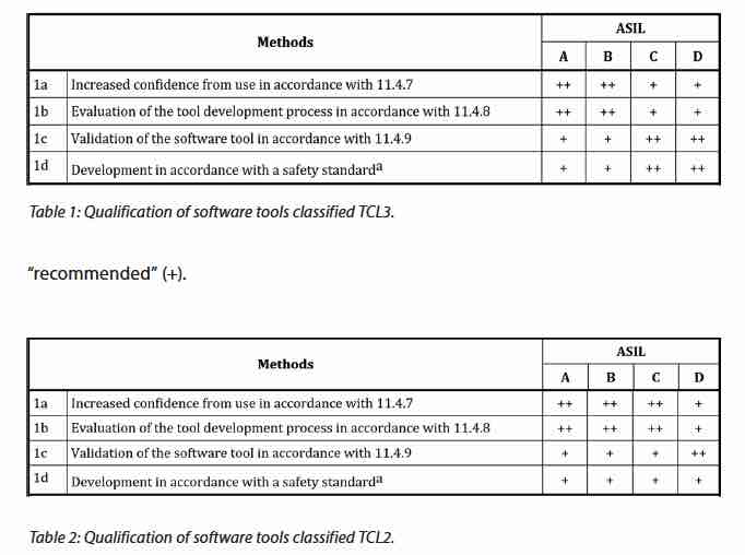
Bronco Webinar 800x100 1

Processing Power Driving Practicality of Machine Learning

Processing Power Driving Practicality of Machine Learning
by Tom Simon on 03-02-2018 at 7:00 am

Despite their recent rise to prominence, the fundamentals of AI, specifically neural networks and deep learning, were established as far back as the late 50’s and early 60’s. The first neural network, the Perceptron, had a single layer and was good certain types of recognition. However, the Perceptron was unable to learn how to handle XOR operations. What eventually followed were multi-layer neural networks that performed much better at recognition tasks, but required more effort to train. Until the early 2000’s the field was held back by limitations that can be tied back to insufficient computing resources and training data.

All this changed as chip speeds increased and the internet provided a rich set of images for use in training. ImageNet was one of the first really significant sources of labeled images, the type needed to perform higher quality training. Nevertheless, the theoretical underpinnings were established decades ago. Multilayer networks proved much more effective at recognition tasks, and with them came additional processing requirements. So today we have so called deep learning which boasts many layers of processing.

While neural networks provide a general-purpose method of solving problems that does not require formal coding, there are still many architectural choices that are needed to provide an optimal network for a given class of problems. Neural networks have relied on general purpose CPU’s, GPU’s or custom ASICs. CPU’s have the advantage of flexibility, but this comes at the cost of lower throughput. Loading and storing of operands and results creates significant overhead. Likewise, GPU’s are often optimized to use local memory and perform floating point operations, which together do not always best serve deep learning requirements.

The ideal neural network is a systolic network where data is moved directly from processing element to processing element. Also, deep learning has become very efficient with low precision integer operations. So, it seems that perhaps ASIC’s might be the better vehicle. However, as architectures of neural networks themselves evolve, ASIC might prematurely lock in an architecture and prevent optimization based on real world experience.

It turns out that FPGA’s are a nice fit for this problem. In a recent white paper by Achronix, they point out the advantages that FPGA’s bring to deep learning. The white paper, entitled “The Ideal Solution for AI Applications — Speedcore eFPGAs”, goes further to suggest that embedded FPGA is even more aptly suited to this class of problems. The paper starts out with an easily readable introduction to the history and underpinnings of deep learning, then moves on the specifics of how processing power has created the revolution we are now witnessing.

Yet, conventional FPGA devices introduce their own problems. In many cases they are not optimally configured for specific applications. Designers must accept the resource allocation available in commercially available parts. There is also the perennial problem of off chip communication. Conventional FPGA’s require moving the data through IO’s onto board traces and then back onto the other chip. The round trip can be prohibitively expensive from a power and performance perspective.

Achronix now offers embeddable FPGA fabric, which they call eFPGA. Because it is completely configurable, only the necessary LUT’s, memories, DSP, interfaces, etc. need to be included. And, of course, the communication with other elements of the system are through direct bus interconnection or an on-chip NoC. This reduces silicon that is needed for IO’s on both ends.

The techniques and architectures used for neural networks are rapidly evolving. Design approaches that provide maximum flexibility require experimentation and evolution. Having the ability to modify the architecture can be crucial. Embedded FPGA’s definitely have a role to play in this rapidly growing and evolving segment. The Achronix white paper is available on their web site for engineers who want to look deeper into this approach.

Read more about Achronix on SemiWiki.com

Related Blog


Robust Reliability Verification – A Critical Addition To Baseline Checks

Robust Reliability Verification – A Critical Addition To Baseline Checks
by Alex Tan on 03-01-2018 at 12:00 pm

Design process retargeting is acommon recurrence based on scaling orBOM(Bill-Of-Material) cost improvement needs. This occursnot only with the availability of foundry process refresh to a more advanced node,but also to any new derivative process node tailored towards matching design complexity, power profile or reliability needs. While many design companies rely on foundry supplied baseline DRC (Design Rule Checks) and LVS (Layout Versus Schematic) rule decks that correspond to each process roll-out, the shift to new technology such as FD-SOI(Fully Depleted Silicon On Insulator) and FinFET injected more complex design verification needs.

During the past five years, the continuous process migration prompted DRC rules explosion in term of complexity and quantities such as due to multi-patterning, voltage-aware DRC, or FinFET specific requirements (e.g. cell alignment, polygon shift). Figure 1 shows the trend. Hence, the traditional DRC rule based verification which involved running foundry rule-sets is no longer adequate. Instead, a robust reliability verificationenvironment is necessary to ensure a successful tape-out. In fact, foundry selection is increasingly hinged upon its availability.

Intellectual Property (IP) reuse is an integral part of a design refresh and is taking a significant portion of design remapping efforts in addressing these aspects:

  • IP porting needs (physical footprint, power target, etc.)
  • IP validation in new context and across different IP’s.
  • If process scaling involved, handling special IP design aspects such as the Electro-Static Discharge (ESD) requirement for IO pin protection and its adjoining interconnect.
  • Validation of IP interaction at full-chip context to further complement stand-alone block level checks, which includes performing its reliability verification.

There are a few key aspects covered in reliability verification as illustrated in Figures 2 and 3:

  • Design level ESDESD is widely known and normally causes irreversible circuit damage. Several protection schemes to mitigate this includes common double-diode ESD network. Mentor’s Calibre PERC high-level checks GUI enables the description of these protection circuits in the form of a Calibre rule-check with minimum effort.

  • Device levelElectrical Over Stress (EOS)EOS could be described as a thermal induced damage due to over-voltage or over-current application to a device.In low-power applications, the presence of high-voltage signals and the use of thin oxides introduce vulnerability of layout to electrical overstress and may lead to oxide breakdown. In multi-voltage domain design, depending on how nets traverse within a design, signals of different voltages may be near each other. This difference in voltage values can create electrical fields that can influence sensitive areas on the chip and lead to reliability issues, particularly for automotive and other high power applications. To protect these nets from Time-Dependent Dielectric Breakdown (TDDB), usually caused by having nets too close to each other for their respective voltages, additional spacing rules are developed that specify power domain spacing based on the voltage delta.Calibre PERCtool voltage propagation feature enables designers to perform automated static analysis on large designs efficiently.

  • Voltage Aware DRCOnce netlist is extracted from the layout, Calibre PERC traces voltages throughout a design without the use of SPICE simulations or manual markers. It identifies nets and devices subject to voltage-aware DRC constraints, pinpoint nets voltages of interest and its gradient with relevant net counterparts then used them to run DRC net spacing checks. These checks not only enable robust protection against TDDB, but also enable design teams to save significant design space by applying only the spacing required for each voltage combination.

  • Interconnect Robustness Checks – Interconnect linking IP to the ESD protection circuitries at device level by using Point-to-Point (P2P) or assessing Current Density (CD) violation to complement chip-level validation. Charge Device Model (CDM) checking is crucial on gates that are directly connected to power/ground due to shrinking gate-oxide thickness.


Most foundries nowadays have provided baseline reliability rule decks and leveraging Calibre PERC reliability platform. TSMC rolled-out TSMC9000IP for both library and IP quality management program. On supported nodes all TSMC IP’s with 100% score have been validated by Mentor’s Calibre PERC. Moreover, itwas selected as the EDA reliability platform by the RESCAR2.0 program. It is driven by a consortium of six major car and supplier companies (Audi, BMW, etc.) and the German government. Their aim is to enhance the reliability and robustness electronic automotive components, which reflects conformance to the international functional safety standard ISO 26262. The collaboration has also yielded Calibre automotive reliability checks. Tower Jazz is the first commercial foundry to incorporate them into their standard Calibre PERC design kit offering.

In summary, demanding markets such as automotive and IoT dictate rigorous need of both internal and third-party IP’s validation, which should include reliability verification. A more streamline and robust set of checks is crucial to complement foundry-provided, rule based checks. Mentor’s Calibre PERC platform provides such design kit and accommodates further customization needs to satisfy such demands. For more info on Calibre, please check Mentor’s white paper here.


Concluding Inconclusives

Concluding Inconclusives
by Bernard Murphy on 03-01-2018 at 7:00 am

Formal methods are a vital complement to other tools in the verification arsenal, but they’re not without challenges. One of the more daunting is the “inconclusive” result – that case where the tool seems to be telling you that it simply gave up trying to figure out if a particular assertion is true or false. Compounding the problem, these inconclusive results aren’t rare events; they can actually be quite common, especially when you’re still on the learning curve. When I was first introduced to formal I thought that this made formal at best a minor tool in verification. If proving assertions was this hit-and miss, how could it play a major role?

Turns out I was wrong, but I had to learn a bit more about formal methods to find out why. An inconclusive result doesn’t mean that all hope is lost for that assertion. As in most things, you can try harder or you can try smarter to prove the assertion. You can also change your approach to the proof. Mentor recently released a white paper illustrating some of these methods through a flow and an example. I particularly like the example so I’ll focus on that here.

This is based on an ECC-wrapped memory, common enough, especially in safety-critical designs. The function reads a (vector) data input and forwards that together with a syndrome value to (in this case) a FIFO. The decoder pulls entries from the FIFO and outputs the data. Through this process, errors in two bits or less can be corrected. So a natural way to approach a formal proof would be to assert that the output data should always be equal to the input data, add a mechanism to inject errors on 0, 1 or 2 bits, then launch the formal prover.

If you do this, you’ll probably get lots of experience with inconclusives, thanks to the fairly complex logic in the encoder and decoder and long sequences that must be followed through the FIFO. So the first trick is to break the design into pieces; in this case, first bypass the FIFO and prove that the assertion always holds when the output of the encoder is connected directly to the input of the decoder.

How do you inject errors? The white-paper suggests a common approach with a clever wrinkle. A simple way to error a data bit is to cut that line, which you can accomplish through an external “cutpoint” command. A formal engine will assume a cut line can take any possible value and will test for all of those values, some of which will obviously differ from the (pre-cut) input values.

You want to test that the ECC will recover from errors on two or less bits, so you need to add two or less of these cuts, but it would be cumbersome to list all of the possibilities, so here comes the wrinkle. The paper suggests adding a random bus with the same width as the data bus, also undriven, so formal will consider all possible value on the bus. Then cutpoints are added to those bits on the data bus where the corresponding bit on the random bus is high. Finally, the proof is constrained to only consider cases where two or less bits on the random bus are high. In this way the formal engine does the hard work of iterating over possible combinations of errors during the course of proving.

Finally, you need to prove that the FIFO operates correctly. The good news here is that formal tools generally provide a support library (assertions and possibly constraints) to deal with common components. For example, the Mentor Questa formal tool has a predefined setup to handle FIFOs. Since you are just checking the FIFO, you can cut the data and syndrome inputs to the block, allowing the proof to consider any possible values.

You might want to do one more thing – add a couple of constraints to avoid potential false errors. If read-enable is issued when the FIFO is empty or write-enable when the FIFO is full, that could be considered out-of-spec usage, or at least beyond the bounds of this proving task. Your choice, depending on what you want to prove. Either way, you can now run a proof using the pre-packaged assertions/constraints and verify the FIFO behaves correctly under all conditions.

In summary, inconclusives are manageable, in this case by breaking the problem down into pieces and through judicious use of cutpoints, constraints and a pre-existing assertion-model for the FIFO. You just have to approach the problem in the right way. You can read the white-paper HERE.


PCB Design in the Cloud

PCB Design in the Cloud
by Daniel Payne on 02-28-2018 at 12:00 pm

I remember meeting John Durbetaki at Intel where we both worked in 1980, it was an exciting time and something called the Personal Computer had just been introduced by companies like Commodore, Apple and Radio Shack (yes, Radio Shack). IBM was rather late to the party with their PC in 1981, however when IBM entered the market then the business world decided that personal computers could be used for business and even scientific purposes. I bought a Radio Shack TRS-80 home computer, but my Intel friend John Durbetaki bought the IBM PC and soon started coding what would become a PCB schematic capture system called SDT under the company name of OrCAD in 1985. The growth of the PC and OrCAD continued and OrCAD went IPO in 1995, then was acquired by Cadence in 1999. What impresses me most is that Cadence has continued to invest in OrCAD over the years, so to learn more I talked with Kishore Karnane in February and discovered that OrCAD had now jumped from just the desktop into the cloud.

Back in 2017 the OrCAD Capture Cloud tool was introduced as a subset of the desktop version, providing lots of benefits like:

  • No need to install software on your desktop, instead just use a web browser with an account
  • Search the Arrow parts catalog
  • Platform independent design

So what’s brand new for 2018 is something they’ve dubbed OrCAD Entrepreneur, and you get lots of useful features for front-end PCB design like:

  • Schematic capture in the cloud
  • Arrow parts catalog with some 4,000,000 parts and symbols
  • Quickly create a BOM
  • Find out lead times for each component
  • See if the parts are in stock
  • All for just $99/year as a time-based license (TBL)

When you browse the Arrow catalog you’ll quickly notice that parts not in stock are shown in bright red, so it’s a best practice to find another comparable part early in your design process instead of much later when it becomes harder to make changes.

So the Cloud is where you do all of the schematic capture, then when it looks OK it’s time to do some simulation on the desktop along with PCB layout on the desktop. In the future you can expect PCB layout in the cloud too, so stay tuned. If you are doing IoT design, then spending just $99/year for schematic capture in the cloud sounds like a bargain, plus it’s backed up with the Arrow parts catalog and 12,000+ reference designs that Arrow has assembled so you don’t need to start with a blank schematic for your next design.

I was curious, so created a free account at https://orcad.arrow.com/arrow/signin to see what OrCAD Capture Cloud was like, and was pleasantly surprised to see a reference design appear using the venerable 80C51 microprocessor:

I was able to move components around, add components, wire between pins, and get a parts report, pretty slick and simply intuitive. Here’s a quick comparison between OrCAD Capture Cloud (free) and the new OrCAD Entrepreneur ($99/year):

So when you choose Cadence tools like OrCAD Entrepreneur you can scale up to using OrCAD on the desktop, or even Allegro for the most sophisticated PCB layout, Analog Mixed signal simulation, signal integrity analysis, or even FPGA design. You can even ask for some expert advise by hiring Arrow for consulting on design services, another way to reduce risk for a new product introduction. The free version of OrCAD Cloud already has 7,000 users, so you can expect a lot of those engineers and students will be upgrading to the OrCAD Entrepreneur version soon.

You can read the original press release about OrCAD Entrepreneur from January 29, 2018 here online.

Summary

If you’re doing system-level design or IoT design and want to start working in the cloud to save time, effort and money, then consider checking out what Arrow Electronics and Cadence have done with the new OrCAD Entrepreneur approach that uses the convenience of the cloud at just $99/year.

Related Articles


CEO Interview: Rene Donkers of Fractal Technologies

CEO Interview: Rene Donkers of Fractal Technologies
by Daniel Nenni on 02-28-2018 at 7:00 am

We (SemiWiki) have been working with Fractal for close to five years now publishing 25 blogs that have garnered more than 100,000 views. Generally speaking QA people are seen as the unsung heroes of EDA since the only time you really hear about them is when something goes wrong and a tapeout is delayed or a chip is respun.

FinFETs really changed QA by introducing many more complexities that require an increasing number of timing, power, and noise characterization checks for example. The foundries and leading edge companies are forgoing internal tools in favor of Crossfire from Fractal where they can collaborate (crowdsource) and increase QA confidence.

The fractal people and I have crossed paths many times over the years working for some of the same companies and recently I joined Fractal for business development work that you will be reading about moving forward. Fractal really is an impressive company with a unique approach to a very challenging market segment. It is my hope that Fractal can be an example to other emerging EDA companies who want to solve problems others have not addressed in a very sensible way, absolutely.

Tell me a little about your background. What brought you to running Fractal?

I started my career at Sagantec. This is how I got involved in the EDA industry. I have a financial background, then became responsible for WW customer support and Operations Management. Seven years ago we noticed a need in the design community for a standardized approach to quality assurance that could replace internal solutions, so Fractal was established by the 3 founding members and I ended up taking the CEO role.

Given our previous experience, we decided to build Fractal with the 3 founders as the only shareholders. Our strategy is to grow the company by adding customers and investing the returns from PO’s in software- and application-engineers. Looking at where we are today I would say we successfully pulled this off. Fractal now has a total of 20+ customers, 50% of which are top 20 Semiconductor companies, at the same time we always have several evaluations ongoing so we’re looking at good continued growth prospects.

Why in your view is library quality important? What is the impact of library errors?
Interesting you ask about libraries because when looking at the usage of Crossfire, our IP validation solution, 25% is on Standard Cell Library and 75% is on other IP such as IOs, Analog, SRAM, Mixed Signal, SerDes etc.

Any error in your IP design data is a potential risk for your design. Finding errors in IP models at the end of a design project could create a huge problem for meeting your tapeout deadline. For example, characterization issues are notoriously hard to spot without rigorous checking. For a standard-cell library at an advanced node we are literally talking Terabytes of .lib files. Now suppose one of those process corners had characterization issues, without QA incoming inspection these will pop-up as issues during timing and power verification. It’s then difficult very late in the design-cycle to trace these back to the characterization, get everything fixed by the library provider only to then see the real timing and power issues coming from the design.

This is why our philosophy at Fractal is to look beyond just qualifying the library or IP before it is used in the design. IP vendors and users need to be aligned on IP quality requirements. For which we have designed the Transport formalism for unambiguously describing QA requirements that can be used as a hand-off between IP consumers and provides, very much like how a DRC deck is used.

Where is this an issue – foundation IP, hard IP, hardened versions of soft IP, internal IP, external IP, …? Which of these tends to create more problems?
First a general remark applicable for all IP used by our customers. IP validation is all about the quality of your design data. Having an IP validation solution in place used by all of your internal design teams will enforce a minimum level of quality on your design data. If this same IP validation can be used on external IP providers you ensure this base-level is applicable for all IP used in your design flow. Our customers do this through Crossfire Transport, a formalism in which they can unambiguously express their quality requirements. These Transport decks can then be used by their IP providers, either internal or external, to ensure IP releases are compliant before they are shipped.

The next step is to gradually add more checks to the Transport decks and discussing the criteria with the IP providers so both parties support these QA requirements and see a benefit in making sure they are met.

This brings me to the different categories you indicated in your question. In general, regardless of the category, the problem is the same: if an IP issue shows up very late in the design flow, that has a danger of violating your schedule and at the very least demands a lot more effort from the design team which cannot be spent on the design itself. For the different IP categories the mechanisms are different though. A Hard IP block may show GDS or LEF vs SPICE mismatches when a black-box representation is replaced by the real model before final verification. A hardened Soft-IP may be slightly deviating from RTL – and perhaps for good reason but your LVS-checker or router doesn’t know that!

What we see with our customers as an important distinction is the difference between internally designed IP and externally sourced IP. Internally designed IP is almost always easier to deal with as the design groups will be using the same CAD flow, base-libraries, naming conventions, etc. So the result is very likely matched with the design in which it needs to be integrated.

External IP on the other has none of these “natural synergies”. However skilled the external designers, there’s fairly high chance some aspects of it won’t match with your design or verification tools or with the other IP blocks deployed in the design. That’s why it’s important to have these characteristics that make an IP block seamlessly integrate captured in a formalism like Transport. And it takes a couple of iterations to get there, as for many of these issues, they’re obvious to you as a user so it’s hard to imagine they’re not obvious to your IP provider.

If we can agree on a standard for IP validation at least everybody that is involved in IP quality will use the same solution which makes the exchange of setups and reports possible. If you can provide your IP supplier with an IP validation setup that meets your QA standards, and tell him to run it before shipping any IP, we are sure that problems with using external IP on your SOC will be minimal.

Why shouldn’t I expect library providers to fix their own problems?
First of all, in spite of all good intentions, library providers are not library users. Unless you explicitly inform them of your library QA requirements you cannot be sure that a library delivery is compliant.

Another part of the answer is that for library providers to fix their own problems we should give them the means to do so. From a QA point of view I am convinced that you should check your design data with a different, preferably independent tool. Checking your design data with same tool / provider that creates your design data could be a problem. How can you expect to find issues with same tool / provider that created your design data in the first place? Part of our existence is because we are tool and provider independent, Crossfire is not an IP or library generation tool, nor is it part of an SoC design flow. This makes it ideally suited as an independent, third-party, validation solution.

Don’t design teams figure out ways to patch together their own solutions? What’s wrong with that approach?
This is the historic approach we see at all our customers since there was no commercial alternative available on the market. And let’s face it, that’s what engineers are really good at: give them a problem and they’ll find some way of fixing it or working around it. Consequently, each design-company built its own IP validation solution, mostly a scripting environment. With no alternative solution available there is nothing wrong with this approach. During most of our evaluations we are benchmarked against such an internal solution.

Of course, we think proprietary solutions do have disadvantages:

  • Who is maintaining this own solution? What if engineers leave the company?
  • Same for, who is updating the own solution when adding new formats and checks for example because company moves to smaller technology node
  • Proprietary solutions most of the time only work for internal IP, doing incoming inspection of external IP is not possible where sometimes 40-50% of your design exist of external IP

Our typical take on this subject is to integrate those proprietary checks that are really design-style or tooling specific within Crossfire, and leave the bulk of the generic checks to a future-proof tool like Crossfire. This way customer get a better overall solution and yet continue to benefit from years of investment in unique proprietary checks.

Why isn’t this a one-time check? Why do we need continuous checking?
The cornerstone of QA is a continuous feedback cycle to improve the overall quality level. If you only run incoming inspection on IP, you’ll be finding the same issues over and over again. What you need is a feedback loop that addresses the root-causes of these issues.

We strongly believe in an IP validation flow used as part of your IP design regression testing. Once you have design data available, why wait with running validation checks till end of your design project? If there are issues, you rather find them as early as possible!

How do you see some of the biggest houses using this today (no names)?
From our 20+ customers, 50% are listed as top 20 semiconductor companies. Certainly, in the last couple of years we have been able to convince these big companies to replace existing internal solutions with Crossfire, our IP validation solution. One of the reasons is that more and more companies agree that maintaining an internal validation solution is not their core business provided a state of the art commercial solution is available on the market.

Another major reason is the adoption of Transport, our formalism for specifying QA requirements. These Transport decks allows customers to export existing Crossfire setups and send them to other internal groups or external IP providers. What we now are seeing is that some of largest fabless customers are demanding Transport compliance for external IP deliveries, very much like a foundry would require DRC-correctness of the GDS. With an internal scripting environment, this will would never have been possible.

Why do you think this problem is going to become even harder and more important to solve going forward?
With smaller technology nodes we see an increase in on-chip variability. This simply drives up the data volume into the terabyte range, so also your QA tools need to be designed from the ground up to deal efficiently with that amount of data. That’s another way of saying “forget scripting”.

On the other hand we see an increasing interconnectedness of design aspects like timing, power, signal integrity and reliability. Your design needs to be optimized for all these aspects at the same time, you simply cannot leave one of them as an afterthought. This leads to increasing demands on the consistency of the different models.

Can you give us any insight into your other thoughts for future trends in the market and for Fractal?
I think that smaller technology nodes will mean more design groups turning towards Fractal as theirs internal solutions will no longer be adequate. Investing more time in such internal solution is a waste for our customers. They should focus on new, better, faster, designs and let us worry about the QA of the design data.

Another opportunity is in the shakeout happening in the providers of smaller nodes, in the end we only see very few foundries offering e.g. N7 manufacturing. This is an excellent opportunity to standardize the QA aspects of libraries and IP blocks targeted for these nodes using Transport and Crossfire as the validation tool. And even if Moore’s law would suddenly come to an end, our belief is that our customers are going to focus even more on their core competencies and their usage of 3rd party IP will remain strong.

I would say, “let’s talk Crossfire” whenever we talk about the Quality of Design Data. If everybody speaks the same Crossfire language, exchange of IP (internal and external) should become easier.

Read more about Fractal on SemiWiki

Also Read:

CTO Interview: Ty Garibay of ArterisIP

CEO Interview: Michel Villemain of Presto Engineering, Inc.

CEO Interview: Jim Gobes of Intrinsix


Hardware Configuration Management – A Key Enabler for Startups & Big Companies Alike

Hardware Configuration Management – A Key Enabler for Startups & Big Companies Alike
by Mitch Heins on 02-27-2018 at 12:00 pm

Software configuration management (SCM) has been around for a long time with commercial SCM offerings such as ClearCase and Perforce and public domain mainstays such as CVS and Subversion. Similarly, over the last two decades we’ve seen a big uptake in the adoption of hardware configuration management (HCM) methodologies driven by the exponential growth in systems-on-a-chip (SoCs) complexity, larger amounts of binary design data, an increased need for better control over data security, and the use of larger geographically-dispersed design teams.

More recently, the complexity growth is being exacerbated by newer heterogeneous SoC architectures required by the internet-of-things (IoT) devices. These devices fuse data from multiple different sensors and some even employ artificial intelligence techniques that combine both hardware and embedded software to process data before sending actionable information back to the cloud.

Managing SoC design data is particularly challenging when one considers that the design data is a composite of many different CAD abstractions and views. Design teams regularly use CAD tools from multiple electronic design automation (EDA) vendors, each which have their own data representations with different and many times incompatible databases. Layer on this the fact that designs also use multiple IP libraries, some built internally while others are from outside vendors.

Add to this the fact that design teams are comprised of engineers with varied backgrounds who are working on different steps of the design process, on different networks and different hardware platforms while geographically dispersed across the globe. These engineers have different responsibilities and access rights to project data that must be strictly enforced.

For any SoC design, it is necessary to effectively manage the sharing of completed design data while isolating data that is still in progress (e.g. shared libraries vs scratch libraries). Hardware teams have traditionally relied on human-based data gate-keeping to ensure engineers don’t inadvertently overwrite each other’s work when copying changes from scratch areas to master libraries. It’s a practice that is fraught with error and almost unmanageable for teams that cross multiple time zones.

Teams have tried to mitigate the time zone problem using multiple master libraries, which they try to keep in sync on a regular basis. The use of hierarchical design complicates this practice as changes to lower level cells may not be seen due to latency between updates to the different master libraries and the lack of a clean bill of materials detailing cell versions to be used by the project. A much bigger problem occurs when changes are not detected and the project tapes out. This sort of error can necessitate a very expensive re-spin. File management is also cumbersome in this arrangement with multiple copies being kept on each site for both use and archival, which increases the cost of the associated storage devices.

The biggest issue aside from the logistical management of files and databases is the lack of a common process for managing the numerous revisions on all views of the design. This is where a hardware configuration management tool comes in. Many companies have taken different approaches to resolving the issues unique to the hardware designer. While some have opted to build layers on top of existing SCMs such as subversion, others have taken the route of creating the HCM from the ground up, providing a better platform which can be easily customized to the different needs of hardware design teams.

SOS7, a HCM from ClioSoft, is a good example. ClioSoft’s SOS7 streamlines the design process and significantly improves a team’s productivity. It acts as a gatekeeper and protects the users from accidentally losing or overwriting valuable data, eliminating the need for manual bookkeeping. SOS7 employs a distributed Client-Server architecture that allows access to data irrespective of a user’s location. Data is stored once in a common project repository and the system makes use of remote cache servers to reduce network bandwidth and minimize the effects of network latency.

Most importantly, SOS7 ensures that design changes are seen immediately by all other members of the team, regardless of the hardware platform used, as SOS7 works cross platform and is available on both the Linux and Windows. SOS7 also provides for sandbox development areas to isolate changing data. Objects checked out for edit have write-locks to prevent accidental overwrites by others with the ability to revert to or view previous versions.

Especially important for safety critical applications requiring ISO 26262 certification is that SOS7 maintains audit trails of all changes made to the design. SOS7 also employs gate keeping policies for data access control and integrates data management with requirements and issue tracking systems such as Jira, Bugzilla and Trac.

While SCM systems deal with source code in the form of ASCII text files, HCM systems must deal with data in different EDA formats. EDA tools create many different types of side files used to manage their own data. Knowing which of these files to archive can be cumbersome, but SOS7 takes care of that automatically, making it easier to add or exchange tools within the design flow as needed. This is enabled by the EDA vendors providing application programming interface (API) support that allows SOS7 to manage their data for them. DM APIs enable the design flow to seamlessly support revision control with automatic check-out and check-in capabilities without requiring the designer to know all the nuances of which EDA files need to be stored and which can be ignored.

It is easy to do a diff with text files, but it is a different problem when it comes to binary files such as schematics or layout views. SOS7 can easily do the text diff capabilities like SCM, but it also goes the extra mile by providing a mechanism to highlight differences between versions of a schematic or layout. In addition, ClioSoft also added design management GUIs directly into the EDA tool library browsers and design editors to give engineers the capability to browse libraries and design hierarchies, examine the status of cells and perform revision control operations without leaving the design environment or learning a new interface.

For most SoC design teams, given the large amount of design data generated, and the increased number of globally dispersed designers, disk space storage remains a major concern. A HCM such as SOS7 works hard to ensure that the size of the repository remains as small as possible. It achieves this objective by intelligently using the notion of symbolic links to optimize disk space usage for static libraries and design files. All the design files in the designer’s workspace remain as read-only symbolic links which minimizes the disk usage considerably. It is only when the designer wants to edit the file that a writable view of the design file is made available in the workspace.

The take away from all of this is that with the advent of more complex SoCs being designed for IoT applications, hardware configuration management will no longer just be for the big enterprises. Even small teams will need to embrace HCM, not only for design complexity, but for the capability to be able to do safety critical designs that require an audit trail and good version control. And remember if you are a startup, you likely will be hoping to be acquired for your IP. Being able to show that your design process and data are clean and in control can make all the difference to an acquiring company as to whether your IP is considered valuable or a pile bones that only a few people can make work.

This all bodes well for ClioSoft and their DM solutions and I expect we will be hearing more from them as the IoT revolution continues to explode.

See also:
ClioSoft Products Overview
ClioSoft SOS – Virtuoso
ClioSoft Visual Design Diff


Connecting Coherence

Connecting Coherence
by Bernard Murphy on 02-27-2018 at 7:00 am

If a CPU or CPU cluster in an SoC is the brain of an SoC, then the interconnect is the rest of the central nervous system, connecting all the other processing and IO functions to that brain. This interconnect must enable these functions to communicate with the brain, with multiple types of memory, and with each other as quickly and predictably as each function requires. But it must also be efficient and ensure error-free operation.

Pulling off this trick has led to plethora of bus protocol standards, most widely represented by the AMBA family, now complemented by CCIX, which I’ll get to later. There’s a nice summary of the various AMBA protocols here, ranging from APB and ASB, through multiple flavors of AHB and multiple flavors of AXI, all the way up to ACE (also in a couple of flavors) and finally CHI. Why so many? Because you simply can’t serve in one protocol the needs for functions running at tens of MHz to functions running at GHz, and quality of service (QoS) ranging from best-effort (e.g. web response) to guaranteed (e.g. phone-call).

Network-on-chip (NoC) architectures, like the FlexNoC solution from Arteris, have become pervasive in mixed-protocol SoC designs because of the flexibility, performance, QoS and layout- and power-efficient advantages they offer in in contrast to more traditional switch-matrix solutions. You don’t need to construct tiered hierarchies of interconnect to bridge between different protocols; the NoC architectures seamlessly manages bridging and communication and can be tuned to deliver the PPA and QoS you need.

These days, there’s another wrinkle: Cache-coherent protocols have become popular thanks to the appearance of CPU clusters and other devices which need to communicate with those systems. When cores read and write memory, they do so first to their caches as a fast short-cut to reading and writing main memory. But if a core updates memory address X in its private cache just before a function F reads X, from its private cache or directly from main memory, then F is going to read the wrong value. Cache-coherency protocols manage these potential mismatches through a variety of techniques to ensure that memory views stay in sync when needed. The ACE and CHI protocols were introduced to cover this need; ACE first then CHI later to handle the more complex configurations appearing in more recent SoCs.

Now of course many design enterprises have a mix of IPs with either ACE interfaces or CHI interfaces. Arteris introduced their Ncore version 3 cache coherent interconnect at the October 2017 Linley conference to manage both ACE and CHI protocols in one interconnect, so you can manage a complete cache-coherent domain with just one interconnect solution. This is technology is very configurable, not just in the expected parameters but also in topology. Ncore 3 supports tree, ring and mesh topologies and even a 3D options, all allowing for different ways to manage bandwidth, latency and fault-tolerance.


Typically, your whole design won’t require cache-coherence; much of what you repurpose from legacy subsystems (or even many new subsystems) won’t depend on this capability. You can connect all of those non-coherent subsystems and hardware accelerators using the standard FlexNoC solution, but again with a wrinkle: A hardware accelerator/sub-subsystem in this non-coherent domain can share address space with the coherent domain, allowing memory references from that accelerator/subsystem to be coherent. You accomplish this by connecting these non-coherent subsytems to the Ncore 3 fabric through interfaces containing proxy caches, which loops them into the coherence management logic. You can even connect multiple non-coherent accelerators to a single proxy cache, thereby creating a cluster that can interact with the rest of the system as a coherent peer to the cache-coherent CPU clusters..

Kurt Shuler (VP Marketing at Arteris) told me that this need to integrate non-coherent subsystems and accelerators with the coherent domain is becoming increasingly important in machine-learning use-cases. As the number of hardware accelerators required to process neural net and image processing algorithms increases, it become harder to manage data communications without using cache coherence for critical parts of the system. Incidentally, it’s also possible to connect, cache coherently, to other die/devices though the CCIX interface (in a 2.5D/3D assembly solution for example). Ncore 3 supports this kind of connection with a CCIX interface connecting coherent domains between multiple chips.

There is one more important set of capabilities in Ncore 3 that are highly relevant to automotive or other safety-critical applications. This solution provides (within the fabric) ECC generators and checkers for end-to-end data protection, intelligent unit duplication and checking, similar to dual-core lockstep (DCLS), and a fault controller with BIST that is automatically configured and connected based on the designer’s data protection and hardware duplication settings. The capabilities can be combined to provide sufficient diagnostic coverage to meet automotive ISO 26262 functional safety certification requirements, as well as the more general IEC 61508 specification.

There’s a lot of technology here which should be immediately interesting to anyone building heterogeneous coherent/non-coherent SoCs and anyone wanting to build added safety into those systems. You can learn more HERE.


Developing Affordable IoT Systems

Developing Affordable IoT Systems
by Daniel Payne on 02-26-2018 at 12:00 pm

The IoT market opportunities in segments like wearables, vehicles, home, cities and industrial are all growing thanks to the combination of semiconductors, sensors, software and systems technology. New hardware designs for IoT edge devices appear on a daily basis, and the companies behind these new products can often be start-ups or just a handful of people in a larger company doing something totally different. Of course to run a successful business you have to manage cash flow, so ideally when starting a new IoT project the expenses need to be managed closely during the design phase. Maybe you need to get an early IoT prototype completed as proof of concept in order to secure funding for production.

IC Insightsproduced a report in June 2017 that showed that the IoT market size in 2016 was $74.6 billion, project to reach $124.1 billion by 2020 in the five categories mentioned above. The IoT edge market doesn’t include gateways, servers, computers, smartphones or tablets.

The five IoT market segments fuel semiconductor revenue in the following proportions where smart cities is the largest segment at 59% or $10.82 billion, followed by Industrial IoT at $4.02 billion and connected vehicles at $2.14 billion:

Custom SoCs are a popular IoT implementation approach for edge devices in order to get the most battery life, performance, lightest weight or smallest sized product. Alternate approaches like placing discrete components on a PCB may not meet requirements. Using a custom SoC does provide several benefits over discrete parts, like:

  • Lower BOM costs
  • Smallest size
  • Lowest power, longer battery life
  • Higher performance
  • Better reliability
  • No more obsolete components
  • Greater IP protection, harder for competitors to copy
  • Higher barriers to entry for your competitors

Before you get all enamored with the idea of developing a custom SoC it is wise to consider your costs, market size and segmentation, time to market, your competitors and the proper process node. Fabricating with a 180nm node is much cheaper than choosing to use 28nm, plus with 180nm you still use 3.3V supplies which provide a high dynamic range and better noise margins, something quite useful for RF antennas.

You’ll hear terms like Non-recurring Engineering (NRE) which include the price of EDA design software, semiconductor IP blocks from 3rd parties and the first silicon run to get your samples. Mentor – a Siemens business, provides a 30 day, no cost evaluation of their Tanner EDA tools for design and simulation of your custom SoC.

  • Schematic capture of AMS design using S-Edit
  • Processor IP – Arm Cortex-M0 or Arm Cortex-M3
  • Analog simulation using T-Spice
  • Digital simulation using ModelSim

Once your proof of concept is ready the next step is to begin implementation using software tools and semiconductor IP. Here’s the flow from Mentor:

Pushing down into the EDA tooling box there are four distinct engineering tasks:

  • IC design
  • Embedded Software
  • System Exploration
  • PCB Design

Analog Mixed-Signal (AMS) design and MEMs design are done with the Tanner EDA tools, and this is also where you model all of the IoT sensors. Here’s more detail on what the AMS IC design flow looks like:

If you’re IoT device needs to measure something like pressure, rotation, acceleration, speed or humidity then MEMS can be modeled in 2D and 3D then analyzed for physical effects.

For embedded software development Mentor Embedded has a real-time operating system (RTOS) and other tools for IoT edge devices. The Nucleus RTOS is well-equipped for battery powered IoT devices and has been used in some 3 billion devices so far. During embedded software development you would use Sourcery CodeBench:

With Sourcery CodeBench your team can use micro-controllers or microprocessors, then understand system execution, measure performance and even debug your apps.

For system-level design and documentation Mentor has the SystemVision Cloud tool that can model both electronics and mechatronics systems, then simulate them so that you can explore the best design approach.

To finally place your SoC and sensors onto a PCB it’s time to use software called PADS Standard, which has both schematic capture and board layout features at an affordable price.

The most popular processor architecture in the world comes from Arm and they have put together a program called DesignStart Evalthat allows you to design and prototype at no cost, then when you’re ready for production you upgrade to DesignStart Pro.

Having IC samples produced at a low cost can be accomplished with multi-project wafers (MPW), where you are sharing the IC mask costs with other companies onto the same silicon wafer. Foundries and companies like MOSIS, eSilicon and EUROPRACTICE can assist you with the MPW logistics. It costs about $16K to get 45 IC samples on a 180nm process, according to EUROPRACTICE, while the second order of 45 samples has an even lower price of $2K.

Your particular SoC for IoT applications may have unique requirements that drive up the cost like adding more IP blocks, including design consulting, needing a smaller geometry process, needing more EDA tools, PCB fabrication, or more analysis of MEMS.

Full production is the final step after your proof of concept has been accepted and raised enough capitol, so you choose a foundry partner and get quotes for mask costs and production. At the 180nm node you can expect mask costs to be around $150K, while more advanced nodes like 90nm you can expect mask costs of $500K.

Summary
The IoT market is very promising and with the right approach you can minimize engineering costs for both a proof of concept and into production using vendors like Mentor and Arm.

There’s a 14 page White Paper from Mentor on this topic, available to download.

Related Articles


The hierarchical architecture of an embedded FPGA

The hierarchical architecture of an embedded FPGA
by Tom Dillinger on 02-26-2018 at 7:00 am

The most powerful approach to managing the complexity of current SoC hardware is the identification of hierarchical instances with which to assemble the design. The development of the hierarchical design representation requires judicious assessment of the component definitions. The goals for clock distribution, power management, and circuit/routing utilization require partitioning that is neither too fine nor too coarse – e.g., the management of multiple power domains within a large partition is difficult, while too fine a partitioning results in more pin constraints to manage and fewer opportunities for timing-driven physical design optimizations.

It struck me that the tradeoffs to the hierarchical representation directly apply to the architecture of an FPGA, as well. I recently chatted with Cheng Wang, SVP of Engineering at Flex Logix Technologies, about how they approached the hierarchical decomposition of the design complexity of their embedded FPGA cores – it was an extremely enlightening discussion.

First, I needed to study up on the typical hierarchical architecture of an FPGA. The programmable logic is implemented with n-input look-up tables (LUT’s). A logic block consists of multiple LUT’s, with additional storage bits. Dedicated local routing connects the LUT’s within the block. The traditional FPGA uses an island style architecture, with logic blocks separated by wiring channels. (This architecture is also denoted as a “mesh” style design.)


Figure 1. General FPGA island architecture. (From: Rose and Betz, “How Much Logic Should Go in an FPGA Logic Block?”, IEEE D&T of Computers, January 1998.)

The input and output signals of logic blocks are connected to segmented wires in the channels. The logic block-to-channel wire assignment is denoted as the “connection box”. The pins of the logic block are connected to a percentage of the wires in the channel (Fc), typically between 50% and 100% of the channel track width.

Figure 2. Expanded view of the connection box and switch box of an FPGA mesh architecture. (From: D. Markovic, “FPGA Architecture”, UCLA EE216B.)

The figure above depicts “un-segmented” channel wires and pass transistors for logic block connections. Alternatively, wire segments are commonly used – the figure below illustrates a block input pin connected to three segments, with the active segment using a buffer + MUX shown in red.)


Figure 3. Segmented wires in the channel connected to a logic block input. (From: V. Betz, “FPGA Architecture”, University of Toronto).

The channel wires are connected to programmable switches, located in the “Switch Box”. The Switch Box design defines how channel wires may connect to wires on other sides – the “flexibility” of the switch box is a parameter that indicates how many other wires are potential connections.

Note in the figures above that clock wires are not shown – the common approach is to include specific global and local wiring tracks for clocks to the logic block storage elements. The dedicated clocks include distributed buffering and clock management units.

FPGA architecture design involves balancing multiple tradeoffs related to the implementation hierarchy:

  • Logic block functionality needs to address performance, utilization, and routability. A fine-grained block design will require more programmable interconnect resources, more switches, and correspondingly, less performance. A very rich (coarse-grained) logic block design will be inefficient for small logic functions. The goal is to find an optimum logic block functionality, which aligns with the capabilities of the logic synthesis and physical design tools. FPGA implementations have commonly ranged from 4-10 LUT’s connected locally in the logic block. As FPGA synthesis has improved, the common LUT design has also evolved, from 4- to 5- to 6-input (with dual 5-input) functionality, as is the case for the current Flex Logix EFLX architecture.

  • FPGA design has also evolved to include special-purpose blocks. The hierarchical implementation needs to be able to readily support the unique programmable logic design of arithmetic and DSP functions.

  • The FPGA routing architecture needs to provide sufficient resources to satisfy both utilization and performance targets.

With that background, I asked Cheng, “How did Flex Logix approach these implementation hierarchy decisions?”

He answered, “Rather than the island architecture, we adopted a hierarchical switch network. The number of switch connections required for routes with high locality is reduced, improving performance.”

Figure 4. Hierarchical switch network for FPGA connectivity. (From: US Patent 9,503,092.)

“Of specific importance is the radix and depth of the hierarchical network tree, which were chosen to optimize the overall routability – the top level of the switch network utilizes the mesh routing of the island architecture.”, Cheng continued.

What other hierarchical tradeoffs were faced?”, I asked.

Cheng replied, “We recognized two key design goals for embedded FPGA IP. For many applications, customers need to implement power gating on some of their eFPGA functionality. And, for performance, customers require optimal, low-skew clock distribution, with support for integrating multiple clock domains. To meet these requirements, we introduced a hierarchical component denoted as a tile.”

The Flex Logix hierarchical tile functionality includes ~2,500 6-input, 2-output LUT’s (16nm), with two optional flops per LUT.

Cheng highlighted, “Within a tile, the programmable logic can be power gated for a low-power application. The tile design includes an optimized H-tree clock, supporting either one or two clock domains. We implemented a novel method for balanced H-tree construction to distribute a clock input across multiple tiles.”


Figure 5. Clock distribution within and between tiles, for balanced H-tree distribution. A clock may enter a tile at any edge, with multiplexing to distribute through a consistent number of buffers throughout multiple tiles. (From: US Patent 9,882,568.)

“With the introduction of the hierarchical switch network and the tile hierarchy for clock and power management, we needed to develop our own netlist placement and routing technology. These algorithms provide improved performance, with a reduced number of switches for logic localized to the lower levels of the hierarchical network.”, Cheng said.

The design of eFPGA IP requires supporting a range of end-customer logic capacities with aggressive utilization and performance targets, while supporting varied clock and power domain designs. The introduction of the hierarchical “tile” achieves these goals.


The next time we get together for coffee, Cheng is going to share how the tile boundary design enables efficient signal communication between adjacent tiles – it should be an interesting discussion.


For more information on these eFPGA hierarchical implementation design options, please follow this link.

-chipguy


Read more about Flex Logix on SemiWiki


LithoVision 2018 The Evolving Semiconductor Technology Landscape and What it Means for Lithography

LithoVision 2018 The Evolving Semiconductor Technology Landscape and What it Means for Lithography
by Scotten Jones on 02-25-2018 at 5:00 pm

I was invited to present at Nikon’s LithoVision event held the day before the SPIE Advanced Lithography Conference in San Jose. The following is a write up of the talk I gave. In this talk I discuss the three main segments in the semiconductor industry, NAND, DRAM and Logic and how technology transitions will affect lithography. Please note the slide numbering used in the article is matched to the slide numbers in the presentation.
Continue reading “LithoVision 2018 The Evolving Semiconductor Technology Landscape and What it Means for Lithography”