It is said that it will cost as much as $600M to develop a 5nm chip. At that price, only a few companies can afford to play, and with that amount of cash in, innovation is severely limited.
At the same time, there is a stampede in the artificial intelligence (AI) market where around 60 startups have appeared, many of which have already raised $60M or more. $12B was raised for AI startups in 2017 and, according to International Data Corporation (IDC), is expected to grow to $57B by 2021. Most of these are going after the data center, which is necessary to get the required ROI when you have a big raise. The chance of success is slim, and the risks are high. There is an alternative for investors and startups.
In this investment thesis, I talk about large disruptive changes happening in the semiconductor industry and the opportunities this creates for innovative architectures and business models.
I used a specific startup – Xceler, who are taking an alternative route to the development of an AI processor. A second organization – Silicon Catalyst is enabling them to bring silicon to market with much lower cost and risk. In the interest of full disclosure, I am a director and investor of both Xceler and Silicon Catalyst.
I love getting feedback and I share that feedback with people, so please let me know what you think. Thanks – Jim
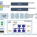
Fig 1. Costs associated with SoC development at each manufacturing node. Source: IBS
Success with semiconductor investment in general, and AI specifically, is a multi-step process. At each stage, the goal is to reduce risk and maximize the potential for success at the lowest possible cost in dollars and time.
The low-risk structured approach comes down to executing the following steps:
- The requirements in the chosen markets are distilled into the minimum functionality required, and target architectures identified.
- The solutions are prototyped using FPGAs and proven in the market, creating initial revenue.
With these two steps, you have proof of technology proficiency and early market validation.
- The solutions are then retargeted to silicon, adding further architectural innovations. An important element of this step is the utilization of silicon incubators that significantly reduce cost and risk. For an AI semiconductor startup, aside for people costs, significant costs are EDA tools and silicon. Typically, this is in the range of $3 to $5M. If the company can avoid or reduce that expense, they will see a much higher enterprise valuation and retain more ownership for the founders and early investors.
Identify the Market Opportunity
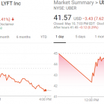
Source: AI Insight, August 30th, 2018
The AI/ML market in the data center is large. For a lot of applications, data collected at various nodes will move back to the data center. These are the public clouds such as those run by large data center companies. The problem for a semiconductor company, or sub-system vendor, is the business model associated with AI/ML in the datacenter. Systems and semiconductor companies build hardware and tools that are powerful and can run a multitude of applications, but the question is what type of AI/ML and what specific applications? It is a solution looking for a market. You need something that people would want to use.
The Cloud provides the infrastructure that your accelerator is integrated into, and they sell repeated services/applications on top of it until the product reaches the end of life. That is not a sustainable business for the technology provider. You can only sell so many units and you can’t keep selling the same volume every year. Consider how NVIDIA’s GP/GPU sales are tapering off. Sales are typically tied to the silicon cycle where every few years more silicon at a lower price, lower power consumption and improved performance becomes available. The services to get customers on board are offered for free, which is the best price, or for cheap, as the service provider is relying on volume sales with a lot of customers/users. This drives the commoditization of the underlying infrastructure as the service providers want the infrastructure at a price that makes business sense for them. In addition, with the slowing of Moore’s law, this forced obsolescence of technology is no longer a driving factor.
The ideal target is a problem looking for a solution, and for Xceler, it was found in the industrial space. Everybody wants to deploy IIoT (Industrial IoT with AI/ML), but each company is looking for the right solution. Consumer IoT was considered but most of the solutions are nice or cool to have, as opposed to must-have. In the consumer space, there are multiple policy hurdles such as legal, privacy, security, or liability. The adoption of these solutions requires a socio-economic behavioral change in the consumer mindset. It is something that requires a generational adoption cycle and a lot of marketing/PR dollars. Conversely, the adoption of industrial solutions is faster because it is a must-have capability that directly affects their bottom line.
Even though the IIoT market is fragmented, fragmentation can be your friend. Each of the larger companies in this space has a top line revenue of $50 billion per year plus. Even with limited market penetration, it is possible to build a sizeable revenue base. There are many potential end-customers, collectively presenting an opportunity, unlike the data center space where there are only a few end customers.
Predictive training and learning on the edge – the dream is now a reality with AI.
Web-based solutions appear to be free. However, someone is paying for the services. In the case of the web, it is advertisers or people trying to sell products. In the industrial space, suppliers are selling both the hardware and the solution. They are directly providing value to the purchaser and can thus make money from that directly, plus there is the potential for future revenue as more capabilities are added.
Every edge-based application is different. This fragmentation is one reason why people are scared of the edge market. You must have the ability to personalize and adapt to the context in which you are deployed. That requires learning on the edge. Inferencing is not enough. If the link breaks, what do you do? Solutions that only perform inferencing could endanger lives.
Some people are trying to build edge-based platforms. These often contain custom edge-based processors for a specific vertical application. They have the characteristics of very high volume but relatively low average selling price in comparison to Cloud devices.
I asked the founder and CEO of Xceler, Gautam Kavipurapu, about his company’s experience in the development of an edge-based processor and application. “We are running a pilot program for a company that makes large gas turbines. They are instrumented in many ways. Fuel valves have flow controls, sensors record vibration and sound, rotation speed at different stages of the turbine is measured, combustion chamber temperature – about 1000 sensors in total. We process the data and do predictive maintenance analysis.”
When the processor is connected to the machine and without connectivity to the Cloud, which may not exist for security reasons, the profile for the normally functioning system is observed. It builds a basic model for the machine, and over time, that model is refined. When you get deviations, the data from the sensors is cross-correlated in real time to figure out what is causing the anomaly. A connection to the Cloud enables the heavy lifting to build a refined model and make micro-refinements to it. However, there are huge advantages in doing the initial processing at the edge in terms of latency and power.
Define the Right Architecture
Systems need to be architected for the problems that they are solving. “We look at problems as hard real-time, near real-time or user time,” explains Kavipurapu. “Hard real-time requires response times of 5 microseconds or less; near real-time requires response times within a few milliseconds, and lastly, user time can take hundreds of milliseconds or minutes. Consumer applications fall within the last category and usually do not have Software License Agreements (SLAs)[BB2] [BB3] and performance commitments so they can work in concert with the Cloud. For problems that require hard or near real-time responses, relying on the Cloud is not viable as the round-trip time itself will take several milliseconds if it manages to complete at all.
“We have seen edge-processors evolve over time. Initially, machine learning on the edge meant collecting data and moving it to the cloud. Both the learning and inferencing were done in the Cloud. The next stage of advancement enabled some inferencing to be done on the edge, but the data and the model remain in the Cloud. Today, we need to move some of the learning to the edge, especially when real-time constraints exist, or you have concerns about security.”
Prototype and Create Revenue Stream
For this class of problem, it is possible to prototype it in an FPGA. For applications that do not need blistering performance, you can even go to market in the seed round with this solution. This offsets the need for more investment dollars and enables the concept to be validated.
“With Xceler, we started with an FPGA solution. They are acceptable in the market place we are targeting since they have good price/performance and power numbers. They are comparable to x86-based systems in price points and provide higher performance. The only downsides are that the margins are compressed, and certain architectural possibilities are not available in an FPGA solution.”
Migrate to Silicon
To capture more value, you do need a solution that is cheaper, faster and lower power. “That involves building a chip, or Edge-Based Processor (EBU),” adds Kavipurapu. “For the control processor, we are using a RISC-V implementation from SiFive. SiFive does the backend design implementation, reducing the risk for us. SiFive is also a Silicon Catalyst partner. We expect our FPGA solution to translate to between 20 million to about 36 million ASIC gates and so the proposed chip does not have to be that large.”
The only risk that remains is silicon risk. By doing the chip in 28nm, a well-understood fabrication process, the manufacturing silicon risk is minimized. All that remains are closing the design and timing which is a much-reduced problem. We have taken out most of the variability in the design element. In addition, we have restrained our design approach using only simple standard cell design with no custom blocks and no esoteric attempts at power reduction.”
Refine architecture
The FPGA solution cannot run faster than about 100MHz. “With an FPGA, we are also constrained by the memory architecture,” explains Kavipurapu. “For the custom chip, we are deploying a superior memory sub-system. New processing techniques require memory for data movement and storage. For us, to execute each computation, it takes about 15 instructions on an FPGA, which will be reduced to 4 or 5 on the ASIC. In terms of clock frequency, we will be running at 500 MHz to 1 GHz in an ASIC at a much-reduced power.”
Usage of silicon incubator
The goal of Silicon Catalyst is to limit the friction for getting an IC startup to the point they can secure an institutional Series A round by reducing the barriers to innovation. This has provided Xceler with a significant advantage compared to potential competition. While the competition struggles with multiple tape outs to achieve working silicon, burning through their dollars before first revenue, Xceler had first revenue even before the tape out. This happened because of the lower risk strategy and help from Silicon Catalyst and others.
“Silicon Catalyst offers through in-kind contributions from ecosystem partners capabilities for startups to get the tools and silicon they need,” says Kavipurapu. “It enables them to get an A round of funding that is nice in terms of valuation and raise. They bring the ability to prototype a chip at a very low cost. We get free shuttles services from TSMC. We do not have to pony up for chip design tools because there are in-kind partnerships for tools from Synopsys. We have licenses to each tool for 2 years. Silicon Catalyst also has a lot of chip industry veterans. I am not a chip guy and neither is my team. When it comes to silicon, Silicon Catalyst adds a lot of value.”
The result is that Xceler will have working samples for a little over $10M. They have customers and could be breakeven before they get to silicon.
Conclusions
We are in an era where innovation is more important than raw speed, the number of transistors or the amount of money invested. There are opportunities everywhere and getting to market with silicon no longer requires building silicon for extremely high volumes and margins. We are in the age of custom solutions designed to solve real problems and there are countless opportunities at the edge.
I’m convinced that Xceler’ s opportunity is much less risky with the help of Silicon Catalyst and the use of an open source architecture (RISC-V). I believe there will be many companies that will follow a similar path – Jim[RC5].
A Final Note
Gautam Kavipurapu was critical to me in creating this post so I’d like to tell you a bit more about him. Gautam has 20 years of experience at both large and small companies in operations, technology and management roles, including setting up and running geographically distributed teams of over 150 employees (India, US, and Europe). Gautam has 14 issued and several pending patents covering systems, networking, computer architecture. He also has several IEEE conference papers to his credit. Gautam’s team at IRIS Holdings in 2001 demonstrated a “Virtual Router,” a software router (modeled as a dataflow machine similar to Google Tensor) on a PC with NIC cards as part of the IRIS (Integrated Routing and Intelligent Switching) system development (Today’s NFV). His inventions and innovations have preceded major technology to various companies in the storage and computing industry worldwide for millions of dollars and cited in more than 350 issued patents. Gautam has an Executive MBA from INSEAD and a BSEE from Georgia Institute of Technology.