The Intelligence Revolution: TSMC’s OIP Ecosystem Forges the Path to Trillion-Transistor AI Systems

The Intelligence Revolution: TSMC’s OIP Ecosystem Forges the Path to Trillion-Transistor AI Systems
by Kalar Rajendiran on 09-23-2026 at 2:00 pm

Broadest Portfolio of Silicon Validated IP

At the 2026 OIP Ecosystem Forum, the industry narrative shifted from incremental scaling to what TSMC defines as the “Intelligence Revolution.” Akin to the 18th-century Industrial Revolution which transitioned human physical labor to mechanical power, the current era is augmenting human ingenuity through artificial intelligence. We are seeing the birth of workload-specific architectures where AI and human creativity operate in a continuous, high-performance feedback loop.

More Than Two Decades of Collaboration: The OIP Foundation

The Open Innovation Platform (OIP) has matured over twenty years from a standard design-center initiative into the industry’s most formidable collaborative engine. What began as a nascent effort to simplify the path to silicon has expanded into a 90-member powerhouse across six specialized alliances: the Design Center Alliance (DCA), EDA Alliance, IP Alliance, Cloud Alliance, VCA Alliance, and the 3DFabric Alliance.

The scale of this ecosystem is best reflected in its portfolio of over 100,000 silicon-verified, production-proven IP titles. This repository isn’t just for the hyperscalers but increasingly targeted at “Physical AI” too for the migration of advanced intelligence into IoT, automotive, and edge devices. By providing these production-proven building blocks, TSMC ensures that the path to a trillion-transistor system is gated by creativity, not by the fundamental physics of IP validation.

Advanced Silicon and the 3D Packaging Backbone

In the AI era, the “one size fits all” approach to manufacturing has been discarded in favor of aggressive Design-Technology Co-Optimization (DTCO). By concurrently refining process, library, and design flow, TSMC’s roadmap delivers a 2.3X power efficiency gain from the current N3P node toward future architectures like A14.

The real breakthrough, however, lies in circumventing the reticle limit. TSMC’s CoWoS® platform is scaling from 3.3-reticle designs to massive packages exceeding 14-reticles. For those visiting the OIP pavilion, the physical 9.5-reticle design on display serves as a tangible milestone of this progress. By 2029, these massive platforms will support 24x HBM5E stacks, enabled by the compounding effect of SoIC (System-on-Integrated-Chips) logic stacking.

Staggering gains are ongoing, from a trajectory moving from a standard SoC on N7 in 2024 to a complex SoIC A14+A14 stack by 2029.

A 48X increase in transistor count within a single CoWoS package over this 5-year window.

An 87X surge in total compute capacity, defined specifically as Transistors × Speed @ Power (normalized performance within a power envelope).

Next-Generation Memory and Connectivity: HBM5 and Silicon Photonics

As AI workloads move from massive training clusters to “Physical AI” and agentic inference at the edge, memory architecture must become more efficient. TSMC is recognizing key partners (SK Hynix, Micron, and Samsung) for their collaboration on the HBM5 standard. By utilizing the TSMC N3P process for the HBM5 base die, the industry is achieving a critical doubling of bandwidth per energy unit.

On the connectivity front, the TSMC-COUPE™ (Compact Universal Photonic Engine) platform is addressing the looming “interconnect wall.” By integrating co-packaged optics and micro-ring modulators (MRM), TSMC is scaling bandwidth density from current 200Gbps production modulators toward a target of 4Tbps/mm by 2030.

Designing “AI for AI”: The Agentic Shift

The most profound shift discussed at the forum was the “virtuous cycle”: using AI to design better chips, which in turn drive more sophisticated AI models.

TSMC is evangelizing a transition from the traditional human-centric PDK (Process Design Kit) to the TSMC ADK (AI Design Kit). This is a multi-agent framework where AI agents self-learn from TSMC’s technology learning layers (cell selection, pin escapes and routing strategies) to orchestrate workflows autonomously.

Industry leaders are already seeing the impact through specific agentic tools:

  • Digital designers are seeing a 3-5X productivity boost in Place and Route (P&R) iterations
  • Analog design migrations (e.g., N5 VCO to N3 VCO) are seeing 3X to 6X productivity gains

Furthering this “AI-native” push, the OIP “Emerging Technologies Alley” featured six hand-picked startups vetted specifically for their innovations in AI-based EDA and IP, signaling a move to bring “AI-first” smaller players into the inner circle of the ecosystem.

System-Level Co-Optimization: From Silicon to SuperPOD

To support trillion-transistor architectures, TSMC is looking beyond the die to the entire rack through STCO (System-Technology Co-Optimization). This holistic approach treats the AI SuperPOD as a single unit of design.

Optimizing a rack-scale system requires more than just logic scaling; it necessitates advanced power delivery and thermal management. TSMC is integrating Integrated Voltage Regulators (IVR), Metal-Insulator-Metal (MIM) capacitors, and Deep Trench Capacitors (eDTC) to stabilize power delivery, while applying thermal DTCO to manage the extreme heat density of next-generation AI accelerators.

Summary

The trillion-transistor era rests on three strategic pillars:

Relentless Logic and Packaging Innovation: Pushing the limits of CoWoS scaling and A14 transistor density.

Radical Design Cycle Acceleration: Implementing the “Agentic AI” shift via the TSMC ADK to compress years of design work into months.

Holistic System-Wide Optimization: Utilizing STCO to align silicon, power delivery, and thermal management into a cohesive system.

As the OIP ecosystem enters its third decade, it remains the vital infrastructure for this Intelligence Revolution. The combination of agentic design flows and massive 3D integration marks the most significant architectural inflection point in a generation.

Also Read:

TSMC’s CoWoS Capacity to Double by 2028—and Rivals Will Still Win Orders

TSMC’s 2026 OIP Forum to Spotlight the Technologies Shaping the Next Era of Chips

ASML and TSMC’s 12-Inch Photomask Initiative: Technical Significance

Comparison of TSMC CoWoS-S, CoWoS-R, and CoWoS-L

Comparison of TSMC CoWoS-S, CoWoS-R, and CoWoS-L
by Daniel Nenni on 09-22-2026 at 6:00 am

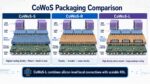
TSMC CoWos Packaging Comparison

Chip-on-Wafer-on-Substrate, commonly called CoWoS, is an advanced packaging platform developed by TSMC. It allows processors, chiplets, and high-bandwidth memory stacks to be integrated within a single package. CoWoS has become especially important for artificial-intelligence accelerators and high-performance computing systems, where processors need enormous memory bandwidth and fast die-to-die communication. The platform has three major variants: CoWoS-S, CoWoS-R, and CoWoS-L. Their main difference is the structure used to connect the components.

CoWoS-S is the original and most mature variant. The “S” refers to its silicon interposer, a large piece of silicon positioned beneath the logic chips and HBM stacks. Fine metal connections fabricated in the interposer provide very dense routing between these components. Through-silicon vias carry electrical signals and power vertically through the interposer to the package substrate.

The principal advantage of CoWoS-S is its excellent electrical performance. Silicon manufacturing supports very fine wiring, enabling high connection density, low latency, and efficient data transfer. Embedded deep-trench capacitors can also stabilize power delivery to demanding processors. These characteristics make CoWoS-S suitable for high-end products requiring predictable performance and extremely wide memory interfaces. Its technology and manufacturing processes are also well established.

However, producing a very large silicon interposer is difficult and expensive. As AI processors grow and incorporate more computing dies and HBM stacks, the required interposer may exceed the dimensions of a conventional lithography reticle. TSMC can combine exposures using mask stitching, but manufacturing complexity and the possibility of defects increase with interposer size. These constraints make continued scaling challenging.

CoWoS-R replaces the large silicon interposer with a redistribution-layer interposer. This structure uses layers of copper wiring and polymer dielectric material to connect the components. Because it does not depend on one large silicon die, an RDL interposer can be expanded more easily to support larger packages. It is also mechanically flexible, which can reduce stress and improve the integrity of package connections.

The trade-off is that CoWoS-R generally has less routing density than CoWoS-S. Its wiring dimensions are larger, so it may not be ideal for the most demanding short-distance die-to-die interfaces. Nevertheless, it provides good signal and power integrity and can be attractive for large HPC systems that prioritize package scalability, design simplicity, and potentially lower manufacturing cost. CoWoS-R entered volume production in 2023.

CoWoS-L combines features of both approaches. It uses an RDL-based interposer for broad package-level routing while embedding small pieces of silicon called local silicon interconnects, or LSIs, at selected locations. These silicon bridges provide dense connections between adjacent logic dies or between processors and memory where the highest bandwidth is needed. Less critical connections can travel through the surrounding RDL structure.

This hybrid design gives CoWoS-L an important balance. It approaches the connection density and electrical performance of CoWoS-S in critical areas without requiring a single enormous silicon interposer. At the same time, it retains much of the scalability and flexibility associated with CoWoS-R. CoWoS-L can also incorporate embedded deep-trench capacitors and other specialized components to improve power delivery and package functionality.

CoWoS-L is therefore particularly well suited to the direction of modern AI hardware. Future accelerators may contain several computing chiplets, larger numbers of HBM stacks, and increasingly complex communication networks. A full silicon interposer may become impractical at these dimensions, while a pure RDL interposer may not provide sufficient density at every interface. The selective placement of LSIs addresses both problems. TSMC began volume production of CoWoS-L in 2024 and is developing increasingly large implementations.

Bottom line: CoWoS-S offers the greatest maturity and consistently dense silicon routing but faces size and cost limitations. CoWoS-R emphasizes scalability, flexibility, and simpler large-package construction, with lower connection density. CoWoS-L provides a hybrid solution, concentrating silicon-level performance where it is most valuable while using RDL technology throughout the rest of the package. Consequently, CoWoS-L is emerging as the most promising option for very large, next-generation AI accelerators, although all three variants remain useful because different products have different performance, cost, and manufacturing requirements.

Also Read:

The Difference Between TSMC CoWoS-S and CoWoS-R

TSMC CoPoS Versus Intel EMIB Semiconductor Packaging

TSMC CoWoS versus Intel EMIB Semiconductor Packaging


TSMC’s CoWoS Capacity to Double by 2028—and Rivals Will Still Win Orders

TSMC’s CoWoS Capacity to Double by 2028—and Rivals Will Still Win Orders
by Daniel Nenni on 09-18-2026 at 8:00 am

TSMC’s CoWoS Capacity to Double by 2028—and Rivals Will Still Win Orders

TSMC reportedly plans to double its Chip-on-Wafer-on-Substrate capacity from approximately 130,000 300mm-equivalent wafers per month at the end of 2026 to 260,000 by 2028. The estimate is not formal company guidance and should be treated as a supply-chain projection. Nevertheless, the direction is consistent with TSMC’s aggressive investment in advanced packaging and indicates that artificial-intelligence infrastructure demand is evolving from a temporary shortage into a multiyear capacity cycle.

CoWoS is a family of 2.5D packaging technologies that places logic dies—such as GPUs or custom accelerators—and high-bandwidth memory on a silicon interposer or redistribution-layer structure. The components communicate through dense, short interconnects before the assembly is mounted on an organic substrate. Compared with routing signals across a conventional circuit board, this architecture provides much higher bandwidth, lower latency and better energy efficiency.

That makes advanced packaging essential to AI performance. Leading accelerators require several HBM stacks to keep thousands of compute units supplied with data. A faster processor has limited value if memory bandwidth, interconnect density or power delivery cannot scale with it. CoWoS therefore is not simply the final step after wafer fabrication; it increasingly determines how much useful compute can be extracted from leading-edge silicon.

Package dimensions are also expanding. TSMC says it certified a CoWoS solution supporting interposers measuring 5.5 times the maximum mask or reticle area in 2025, with volume production planned for 2026. Larger packages can accommodate more compute chiplets, input/output dies and HBM stacks, but they consume more interposer area and packaging resources per device. Consequently, doubling wafer-equivalent capacity does not necessarily double the number of completed accelerators. TSMC’s 2025 annual report also identifies CoWoS, InFO and SoIC as central technologies for large-scale, power-efficient integration.

The expansion should help Nvidia, AMD and custom-ASIC developers raise shipments, yet it may not eliminate the shortage. AI clusters are moving toward larger multi-die packages, while hyperscalers are developing internal accelerators alongside purchases of merchant GPUs. Demand is therefore increasing in both volume and packaging intensity. Yield management, HBM availability, substrates, thermal solutions and testing capacity can remain bottlenecks even when nominal CoWoS output rises.

This imbalance creates an opening for Intel Foundry. Intel’s Embedded Multi-die Interconnect Bridge places small silicon bridges inside the package substrate instead of using a large interposer beneath every die. Foveros adds vertical die stacking, while EMIB-T combines bridge-based connections with through-silicon vias for improved signal and power delivery. These technologies are not drop-in replacements for every CoWoS design; customers must qualify physical interfaces, assembly processes, thermal behavior and reliability. But they offer an alternative route for new custom accelerators. Intel has confirmed that its advanced-packaging portfolio includes EMIB, EMIB-T and Foveros, while MediaTek has publicly said it supports both Intel and TSMC packaging platforms.

Outsourced semiconductor assembly and test providers should capture spillover as well. ASE, Amkor and other OSAT companies can perform portions of package assembly, bumping, substrate integration and final testing, either through cooperation with foundries or through competing 2.5D platforms. Amkor’s Arizona advanced-packaging campus, scheduled to begin production in 2028, illustrates how packaging demand is also encouraging geographic diversification.

Bottom line: Semiconductor leadership is no longer defined solely by transistor density. The ability to combine heterogeneous dies, HBM and high-speed interfaces at acceptable yield and cost now determines accelerator supply. TSMC’s expansion reinforces its leadership, but persistent demand gives Intel and OSAT providers something equally valuable—production orders, customer qualifications and the opportunity to become permanent second sources rather than temporary overflow suppliers.

We will get an update next week at the TSMC OIP Forum but this is where we are at today. Simply incredible, absolutely.

Also Read:

TSMC’s 2026 OIP Forum to Spotlight the Technologies Shaping the Next Era of Chips

Comparing Advanced Packaging from TSMC, Intel Foundry, and Samsung Foundry

Comparing Intel EMIB and Intel Foveros


TSMC’s 2026 OIP Forum to Spotlight the Technologies Shaping the Next Era of Chips

TSMC’s 2026 OIP Forum to Spotlight the Technologies Shaping the Next Era of Chips
by Daniel Nenni on 09-11-2026 at 6:00 am

TSMC OIP 2026

It’s that time of year again. Time certainly flies when AI is chasing you! This year marks the 18th TSMC OIP Ecosystem Forum, and it promises to be bigger and better than ever. My SemiWiki partners, Mike Gianfagna and Kalar Rajendiran, will join me in covering the event live, so stay tuned for all the news that’s fit to print.

Mike and Kalar previously worked at eSilicon, which was both a major SemiWiki sponsor and a TSMC Value Chain Aggregator. Kalar also manages the SemiWiki IP Reports. It really is a small semiconductor world.

TSMC will bring together semiconductor designers, technology partners, customers, analysts and media for its 2026 North America Open Innovation Platform Ecosystem Forum on Wednesday, September 23, at the Santa Clara Convention Center in California. Running from 9 a.m. to 2:30 p.m. Pacific Time, the event will examine how advances in silicon processes, chip packaging, artificial intelligence and electronic design tools are changing the way increasingly complex integrated circuits are built.

The forum’s theme, “Expanding AI with Leadership Ecosystem,” reflects the growing importance of collaboration across the semiconductor industry. Modern chips are no longer created through manufacturing innovation alone. Their development depends on a closely connected network of foundries, design-software providers, intellectual-property suppliers, cloud platforms, packaging specialists and customers. TSMC’s Open Innovation Platform, or OIP, is intended to bring those capabilities together and make them available through validated, production-ready design solutions.

Next-generation process technology will be a central topic. Presentations will cover design flows, methodologies and tools supporting TSMC’s N2, A16 and A14 processes, with particular attention to energy efficiency, multiphysics effects and advanced chip architectures. Attendees will also receive updates on the continuing development of tools and solutions for established and forthcoming advanced nodes, including N3, N2 and processes beyond them.

Advanced packaging will receive comparable attention. The program will explore design solutions for TSMC’s 3DFabric portfolio, including InFO, CoWoS, SoIC and SoW technologies, as well as TSMC-COUPE. These technologies allow companies to combine multiple computing, memory and connectivity components within sophisticated packages or three-dimensional systems. This approach has become increasingly important as developers seek higher performance without depending exclusively on traditional transistor scaling.

The forum will also examine the use of agentic AI in semiconductor design. TSMC’s ecosystem partners are expected to demonstrate how more autonomous AI workflows can improve productivity and optimize both conventional two-dimensional chips and complex 3D integrated circuits. Additional sessions will address solutions tailored to high-performance computing, AI and machine learning, automotive systems, mobile devices and the Internet of Things. Specialty platforms covering ultra-low-power, ultra-low-voltage, analog, radio-frequency and millimeter-wave technologies will round out the technical program.

The agenda begins with registration and breakfast at 8:30 a.m., followed by welcome remarks at 9:30. TSMC keynotes and a guest speech will run until 11 a.m. Afterward, TSMC and OIP partners will lead technical sessions. The event also includes the OIP Partner of the Year Award luncheon and an afternoon visit to the ecosystem pavilion, where participants can examine partner technologies and solutions. Customer case studies will illustrate how collaboration, semiconductor IP and cloud-based design environments can shorten development cycles and accelerate products’ arrival in the market.

Why does this matter? The semiconductor industry is confronting several challenges at once. AI systems require enormous increases in computing and memory performance, but power consumption, heat, manufacturing complexity and development costs are also rising. No single company can solve all of those problems independently. Progress increasingly depends on whether manufacturing processes, design tools, reusable IP and advanced packaging technologies work together reliably.

The OIP Forum therefore serves as more than a showcase for individual technologies. It offers a view of whether the broader design ecosystem is ready to turn ambitious process and packaging roadmaps into manufacturable products. Updates involving N2, A16 and A14 may help indicate how designers will access future gains in performance and efficiency. Developments around CoWoS, SoIC and other 3DFabric technologies are especially relevant to AI accelerators, where closely integrating processors and high-bandwidth memory has become critical.

Bottom line: The attention given to agentic AI is equally significant. If these workflows prove dependable, they could help engineering teams explore more design options, identify problems earlier and manage the growing complexity of 2D and 3D systems. Ultimately, the forum matters because the innovations discussed there may influence the cost, speed and energy efficiency of future computing products—from data-center AI hardware and vehicles to smartphones and connected devices.

Also Read:

TSMC’s Overseas Fabs Are Paying Off

How TSMC Is Wiring the AI Era With Light

A 0.42-Nanometer Breakthrough From TSMC Could Push Transistors Beyond Silicon


ASML and TSMC’s 12-Inch Photomask Initiative: Technical Significance

ASML and TSMC’s 12-Inch Photomask Initiative: Technical Significance
by Daniel Nenni on 09-07-2026 at 11:00 pm

ASML and TSMC’s 12 Inch Photomask Initiative

ASML and TSMC’s proposed shift from 6-inch to 12-inch photomasks is an attempt to redesign a critical but often overlooked part of advanced semiconductor manufacturing. Photomasks are precision plates carrying the circuit patterns projected by a lithography scanner onto a silicon wafer. In extreme-ultraviolet lithography, 13.5-nanometer light reflects from a multilayer mask, passes through the scanner’s projection optics, and prints features in photoresist. Mask quality, size, flatness, defect control, and pattern placement therefore directly affect yield and productivity.

The initiative is tied to High Numerical Aperture EUV, or High NA EUV. Numerical aperture determines how much light an optical system can collect and how finely it can resolve features. ASML’s High NA platform increases NA from 0.33 in conventional EUV systems to 0.55, enabling smaller printed features and reducing the need for costly multiple-patterning steps. However, High NA optics use anamorphic imaging: the pattern is demagnified differently in the scan and non-scan directions. This design controls mirror size but reduces the exposure field available from today’s 6-inch masks.

A smaller effective field creates a practical constraint for large chips. If a design exceeds the field, the scanner must expose separate sections and “stitch” them together on the wafer. Stitching can enable large processors, especially AI accelerators, but it adds design rules, alignment requirements, process complexity, and potential yield risk at the seam. A 12-inch mask offers substantially more pattern area. The larger format could restore or expand the usable field, reducing stitching and allowing more dies, or larger dies, to be exposed efficiently.

The productivity argument is equally important. Lithography tools are among the most expensive and capacity-sensitive assets in a leading-edge fab. A larger mask could contain more exposure content and reduce mask swaps, stage movements, or the number of exposure sequences required for some layouts. Any improvement in wafers per hour spreads scanner depreciation and operating expense across more good chips. That can lower cost per transistor even when the capital cost of High NA systems is exceptionally high.

The transition is not a simple scale-up. A 12-inch EUV mask demands new blanks, substrates, reflective coatings, absorbers, pattern-writing tools, inspection systems, cleaning equipment, handling robots, pellicles, storage containers, and scanner interfaces. Larger masks will be heavier and harder to keep flat, while tiny distortions or particles can print systematic defects across many wafers. The entire metrology and logistics chain must meet nanometer-level tolerances. This explains why ASML and TSMC are organizing an industry-wide initiative years before production: no scanner manufacturer, foundry, mask shop, or materials supplier can create the standard alone.

The announced schedule reflects that systems challenge. TSMC intends to introduce High NA EUV into high-volume manufacturing for advanced nodes beginning in 2030, initially with existing 6-inch masks. The partners target a 12-inch mask pilot line by 2031 and production-ready 12-inch High NA lithography by 2033. This staged approach separates adoption of the new optics from adoption of the new mask infrastructure, reducing the risk of changing both simultaneously.

For chip designers, the benefit could appear as fewer floor-planning compromises and greater freedom to build large compute engines. For equipment suppliers, it creates a demanding development roadmap and a potential new market. For governments, it highlights how semiconductor leadership depends on coordinated, long-horizon investment across a concentrated supply chain.

Bottom line: First, it signals that High NA EUV is moving from a resolution experiment toward an industrial production platform. Second, it anticipates AI-driven transistor architectures with more layers requiring the technology. Third, it seeks to preserve scaling economics: finer features are valuable only if manufacturers can print them at high yield and competitive throughput. Finally, the initiative could establish a new ecosystem standard, creating large investment opportunities but also reinforcing the strategic importance of ASML, TSMC, and specialized suppliers. The real breakthrough is therefore not merely a bigger mask. It is coordinated infrastructure intended to make the next generation of advanced chips manufacturable at scale.

Source: 

Also Read:

Comparing Advanced Packaging from TSMC, Intel Foundry, and Samsung Foundry

TSMC’s Overseas Fabs Are Paying Off

How TSMC Is Wiring the AI Era With Light


Comparing Advanced Packaging from TSMC, Intel Foundry, and Samsung Foundry

Comparing Advanced Packaging from TSMC, Intel Foundry, and Samsung Foundry
by Daniel Nenni on 09-06-2026 at 10:00 am

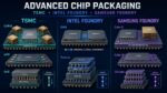
Advanced Chip Packaging Comparison INtel TSMC Samsung

Advanced semiconductor packaging has become essential to improving computing performance as conventional transistor scaling grows more difficult and expensive. Instead of manufacturing an entire processor as one large monolithic die, chipmakers can divide it into smaller chiplets and combine logic, memory, input/output and specialized accelerators within one package. TSMC, Intel Foundry and Samsung Foundry all offer technologies for this purpose, but their portfolios differ in architecture, maturity, market position and integration strategy.

TSMC groups its advanced packaging technologies under the 3DFabric platform. Its principal offerings are CoWoS, InFO and SoIC. CoWoS, or Chip-on-Wafer-on-Substrate, is primarily a 2.5D technology for high-performance computing and artificial intelligence. It places logic dies and high-bandwidth memory, or HBM, on an interposer that provides dense, high-speed connections. CoWoS-S uses a silicon interposer, while CoWoS-L combines local silicon interconnects with a redistribution-layer structure. CoWoS-R relies more extensively on redistribution layers to provide a cost-conscious option for suitable designs.

CoWoS has become especially important for large AI accelerators, where several HBM stacks must communicate with GPUs or custom processors at enormous bandwidth. TSMC says CoWoS-S supports silicon interposers up to approximately 3.3 times the lithographic reticle size, while CoWoS-L and CoWoS-R address larger configurations. TSMC’s InFO family provides fan-out packaging without a conventional silicon interposer and is used where thin profiles, efficient wiring and lower cost are priorities. SoIC addresses true three-dimensional integration by directly stacking dies with dense vertical connections. SoIC stacks can also be incorporated into CoWoS or InFO packages, creating what TSMC calls a “3Dx3D” system. TSMC 3DFabric overview

Intel Foundry’s portfolio centers on EMIB and Foveros. EMIB, or Embedded Multi-die Interconnect Bridge, connects chiplets positioned side by side through small silicon bridges embedded in the organic package substrate. Unlike a full silicon interposer, EMIB places silicon only where dense die-to-die communication is needed. This can reduce silicon usage, simplify some aspects of assembly and allow designers to construct packages larger than a single reticle. EMIB is well suited to connecting compute tiles, I/O dies and HBM while leaving each component relatively accessible for cooling.

Foveros complements EMIB by supporting vertical integration. In a Foveros package, compute chiplets can be stacked on an active base die that provides communication or other functions. Foveros Direct uses copper-to-copper hybrid bonding to obtain finer connection pitches, lower resistance and greater bandwidth between stacked dies. Intel can combine Foveros stacks with EMIB bridges in an EMIB 3.5D package, gaining both vertical density and horizontal scalability. Intel is also expanding the portfolio with variants such as EMIB-T, which adds through-silicon vias, and Foveros-R, a redistribution-layer option intended to balance cost and performance. Intel Foundry packaging overview

Samsung Foundry offers comparable horizontal and vertical integration technologies. Its current horizontal portfolio includes 2.5D Cube-S and 2.3D Cube-E and Cube-R. Cube-S, previously associated with Samsung’s I-Cube naming, places logic chips and HBM on a silicon interposer. Samsung says qualified configurations can use a 3.3-reticle-size interposer and integrate up to eight HBM modules, with larger options supporting additional memory. Cube-E uses embedded silicon bridges, making it conceptually similar to Intel EMIB, while Cube-R employs a redistribution-layer interposer.

For vertical integration, Samsung offers 3D Cube technologies, formerly called X-Cube. The 3D Cube-T variant uses thermo-compression bonding in a chip-on-wafer process, while 3D Cube-H uses hybrid copper bonding for finer pitches and improved electrical performance. These technologies stack dies to shorten communication paths, save package area and reduce the yield risks associated with extremely large monolithic chips. Samsung’s broader strength is its ability to combine foundry manufacturing, packaging and memory expertise within one company—an attractive proposition for systems that depend heavily on HBM. Samsung Foundry packaging overview

Technically, the three companies are converging on similar categories. TSMC CoWoS-S and Samsung Cube-S use large silicon interposers for 2.5D integration. Intel EMIB and Samsung Cube-E use localized embedded bridges instead of full interposers. TSMC SoIC, Intel Foveros Direct and Samsung 3D Cube-H pursue dense vertical stacking through advanced bonding. Each vendor also offers redistribution-layer alternatives that can reduce cost where maximum silicon-interposer density is unnecessary.

Their main differences lie in execution and ecosystem. TSMC benefits from its position as the leading manufacturer of advanced chips for numerous fabless customers, giving 3DFabric and CoWoS a powerful customer base and extensive exposure to AI products. Intel brings long experience packaging its own complex processors and emphasizes flexible bridge-based integration, large package sizes and geographically distributed assembly capabilities. Samsung offers a vertically integrated route connecting logic fabrication, advanced packaging and memory production, although customers must evaluate its particular process maturity, design ecosystem, capacity and product requirements.

Bottom line: There is no universally superior portfolio. TSMC is especially prominent in interposer-based AI packaging; Intel differentiates itself through EMIB and combined 3.5D architectures; and Samsung offers a broad, increasingly unified set of interposer, bridge and vertical-stacking technologies. The correct choice depends on bandwidth, thermal limits, HBM count, chiplet sources, package size, production capacity, cost and supply-chain strategy.

Also Read:

Intel and TSMC Take Different Paths to High-NA EUV

Intel Foundry and the DAC2026 Ecosystem

Executive Interview with James Huang of AlChip


TSMC’s Overseas Fabs Are Paying Off

TSMC’s Overseas Fabs Are Paying Off
by Daniel Nenni on 08-28-2026 at 6:00 am

TSMC's Overseas Fabs Are Paying Off

TSMC’s overseas fabrication strategy is beginning to deliver its intended return: not immediate cost parity with Taiwan, but manufacturable geographic redundancy, closer integration with major customers and access to subsidized capacity in strategically important markets. Arizona and Kumamoto are already producing commercially, while Dresden extends the model into Europe’s automotive semiconductor ecosystem.

The clearest validation is Arizona’s Fab 21. Its first phase entered high-volume production on the N4 process in the fourth quarter of 2024, achieving yields comparable with TSMC’s Taiwanese fabs. Yield parity matters because advanced-node economics are extremely sensitive to defect density. A foreign fab that requires substantially more wafer starts per functional die would provide political resilience but destroy economic value. Arizona has crossed that technical threshold.

Demand is also materializing. Apple, the fab’s first and largest customer, expects to purchase well over 100 million advanced chips from the facility in 2026—a significant increase from 2025. AMD has likewise identified Arizona as a source of leading-edge products. TSMC has therefore accelerated its second Arizona fab, now scheduled for high-volume manufacturing in the second half of 2027. That facility will introduce 3-nanometer-class production, while subsequent fabs are planned for N2, A16 and later technologies. The objective is no longer an isolated factory; it is an independent “GIGAFAB” cluster incorporating wafer fabrication, advanced packaging and research capabilities. (TSMC, Apple)

Kumamoto demonstrates a complementary localization model. Japan Advanced Semiconductor Manufacturing, TSMC’s venture with Sony, Denso and Toyota, began volume production in late 2024 with what TSMC describes as very good yield. Its initial 12/16-nanometer and 22/28-nanometer processes serve image sensors, automotive controllers and industrial devices—markets where supply continuity, qualification history and proximity to customers can be more valuable than transistor density. A second Kumamoto fab is under construction, and TSMC now plans to introduce 3-nanometer technology there in response to AI-related demand. This converts Japan from a specialty-node outpost into a potential advanced-logic base.

Dresden completes the regional segmentation. European Semiconductor Manufacturing Company, owned by TSMC, Bosch, Infineon and NXP, is designed around 300-millimeter automotive and industrial production rather than leading-edge AI accelerators. Its technology portfolio and local joint-venture structure reduce qualification and logistics risks for European customers. Germany’s €5 billion state-aid package offsets part of the structural cost disadvantage of manufacturing in Europe. (European Commission)

The payoff should not be confused with near-term margin accretion. Labor, construction, utilities, supplier density and smaller initial scale make overseas wafers more expensive. TSMC forecasts that foreign-fab ramp-ups will dilute gross margin by two to three percentage points in their early stages and by three to four points later as expansion accelerates. Nevertheless, the company posted a 59.9% gross margin in 2025, suggesting that leading-edge demand, utilization and pricing can absorb the burden. (TSMC Q2 2026)

Bottom Line: The strategic return is therefore risk-adjusted rather than purely accounting-based. Subsidies lower capital intensity; customer commitments improve utilization visibility; replicated process control proves that TSMC’s manufacturing system can travel; and regional capacity reduces exposure to earthquakes, shipping disruptions and geopolitical concentration. Taiwan will remain the center of TSMC’s newest technology and largest scale. But overseas fabs are evolving from expensive insurance policies into productive, customer-backed nodes of a global manufacturing network—and that is precisely how the investment begins to pay off.

Also Read:

How TSMC Is Wiring the AI Era With Light

A 0.42-Nanometer Breakthrough From TSMC Could Push Transistors Beyond Silicon

Intel and TSMC Take Different Paths to High-NA EUV


How TSMC Is Wiring the AI Era With Light

How TSMC Is Wiring the AI Era With Light
by Daniel Nenni on 08-21-2026 at 10:00 am

How TSMC Is Wiring the AI Era With Light

TSMC’s photonics strategy is centered on integrating optical input-output with advanced logic, rather than selling conventional optical transceivers as standalone products. The company is developing a silicon-photonics foundry platform and a packaging architecture called TSMC-COUPE, or Compact Universal Photonic Engine, aimed primarily at AI and high-performance-computing interconnects.

A silicon-photonics die implements optical waveguides, modulators, photodetectors and fiber-coupling structures using semiconductor manufacturing techniques. However, it still requires electronic circuitry for modulation drivers, receiver amplification, clocking and control. In many optical modules, the electronic integrated circuit and photonic integrated circuit are separate dies connected laterally or through package wiring. Those connections add parasitic resistance, capacitance and inductance, increasing power and limiting signaling speed.

COUPE addresses that interface by vertically stacking an electronic die on a photonic die with TSMC’s SoIC chip-on-wafer bonding technology. Fine-pitch, high-density connections shorten the electrical path between driver or receiver circuits and optical devices. TSMC says the structure supports both grating and edge fiber couplers while avoiding cavities and mechanically weak features. The optical engine can then be integrated beside a host ASIC in a larger package.

TSMC has pursued a staged commercialization plan. The first implementation targeted small-form-factor pluggable optics, providing a lower-risk environment for process qualification, device characterization, assembly and reliability testing. The next step is true co-packaged optics, or CPO, in which the optical engines move from the circuit board into the switch or compute package. TSMC announced that a COUPE-on-substrate CPO solution is entering production in 2026.

The company reports that in-package COUPE provides twice the power efficiency and one-tenth the latency of a pluggable board-level implementation. Its platform includes a 200-gigabit-per-second micro-ring modulator, a compact resonant device that converts an electrical data stream into optical modulation. TSMC’s 2025 reporting also says it achieved 200-gigabit-per-second operation with multiple customers and is developing CPO to reduce data-center data-movement energy by more than 50 percent.

Photonics is being tied directly to TSMC’s 3DFabric portfolio. SoIC supplies vertical die-to-die integration; CoWoS can combine optical engines, switch or accelerator ASICs, chiplets and high-bandwidth memory on an interposer and substrate. This is strategically important because an optical link cannot be optimized independently of SerDes circuits, package routing, power delivery, cooling, fiber attachment and test. TSMC can co-design those interfaces while using manufacturing infrastructure already developed for large AI packages.

The immediate application is scale-out networking between racks and potentially scale-up connectivity among accelerators. Electrical channels become progressively harder to drive as data rates and distances increase: insertion loss rises, equalization grows more complex, and retimers consume additional power. Moving the electro-optical conversion closer to the ASIC reduces the length of high-speed copper channels. Optical fiber then carries bandwidth over distance with lower loss.

Significant challenges remain. Micro-ring modulators are compact and efficient but sensitive to fabrication variation and temperature, requiring wavelength control. External lasers must deliver stable optical power without creating thermal or reliability problems inside the package. Fiber attach demands micrometer-scale alignment, while known-good-die screening, optical testing, repairability and yield become difficult when expensive logic and photonics are combined. CPO also changes field service: a failed optical engine cannot be replaced as easily as a pluggable transceiver.

TSMC is separately researching more ambitious photonic computing. It has reported a wafer-integrated digital optical computing system using multilayer photonic fan-out and stacked electronic-photonic dies, with less than 0.08 picojoules per multiply-accumulate operation in an eight-bit, 512-by-512 demonstration. That work is exploratory, whereas COUPE is the near-term commercial focus.

Bottom line: TSMC is treating photonics as a system-integration problem. Its competitive asset is not any single modulator or waveguide. It is the ability to combine a qualified photonics process, electronic control silicon, three-dimensional bonding, interposers, advanced packaging and high-volume manufacturing into a customer-ready platform. That positioning lets fabless chip companies adopt optical connectivity without building their own photonics factories or assembling a fragmented supply chain. If production scales, TSMC could make optical I/O a standardized extension of leading-edge chip design and packaging.

Also Read:

A 0.42-Nanometer Breakthrough From TSMC Could Push Transistors Beyond Silicon

Intel and TSMC Take Different Paths to High-NA EUV

The Difference Between TSMC CoWoS-S and CoWoS-R

TSMC CoPoS Versus Intel EMIB Semiconductor Packaging


The Twelve-Month Rule Does Not Describe a New Fab

The Twelve-Month Rule Does Not Describe a New Fab
by Admin on 08-20-2026 at 10:00 am

capex to wafer starts lag

By Nikhil Shah

Capital spending is often treated as if it becomes semiconductor capacity about twelve months later. That can be a useful rule for equipment installed in an existing fab. It is a poor description of a new fab built from the ground up.

I tested the distinction using five advanced-node projects in the United States where I could source both a construction start and a first-production date. The set covers TSMC, Intel, Samsung and Micron. Measured from the start of construction to first production, the disclosed schedules have a median lag of 45 months and a range of 39 to 60 months.

That is not a new industry rule. Five projects are too few, several dates are only precise to a year, and three of the production dates were still targets as of August 2026. It does show why a twelve-month capex lag and a four-year fab schedule can both be true.

Two different clocks

The shorter clock starts after the shell, cleanroom, utilities and much of the workforce are already in place. In that setting, the marginal dollar buys tools and the relevant delay is procurement, installation and qualification.

The longer clock starts when a company begins a greenfield site. Construction, utility connections, cleanroom systems, equipment installation, process qualification and hiring all sit between the announcement and commercial output. A tool lead time captures only part of that sequence.

TSMC’s Arizona site makes the distinction visible. Its first fab began construction in June 2021 and started high-volume N4 production in the fourth quarter of 2024. TSMC says the structure of its second Arizona fab was completed in 2025, while N3 volume production is targeted for the second half of 2027. Finishing the building is not the same as finishing the capacity.

Intel’s Fab 52 tells a similar story. Intel broke ground on its two-fab Arizona expansion in September 2021. Fab 52 was fully operational in October 2025 and was preparing to reach high-volume Intel 18A production by year-end. The elapsed time was about four years.

Samsung and Micron provide the forward-looking observations. Samsung dates the groundbreaking for its first Taylor fab to 2022. On its first-quarter 2026 earnings call, Samsung said the fab would start operations in 2026 and commence mass production in 2027. I use the 2027 production milestone so the comparison stays consistent. Its second Taylor fab is expected to begin construction by the end of 2026 and target mass production in 2030. Micron formally announced the start of construction on its Boise memory fab in October 2023 and schedules initial DRAM output for 2027.

Why the dates need caution

These milestones are not standardized. A groundbreaking ceremony, the start of continuous construction, structure completion, equipment move-in and volume production are different events, but companies do not always report each one.

Micron is the clearest example. It held a Boise groundbreaking in 2022, then issued an October 2023 release titled “Micron Initiates Construction on Leading-Edge Memory Manufacturing Fab.” I used the later date because it is the company’s explicit construction milestone. Using the ceremony instead would lengthen the same project’s lag by about a year.

Samsung reports some milestones only by year. I placed those dates at the middle or stated boundary of the year and marked the resulting interval with a six-month tolerance. That is better than inventing a quarter, but it is still an estimate.

The sample also mixes two completed projects with three company schedules. Future delays would lengthen the latter observations. For that reason, 45 months should be read as a description of this small disclosed sample, not a forecast with false precision.

The capex-to-capacity ratio is harder to calculate

The same exercise exposed a second problem. To compare capital intensity, a project needs one budget and one planned wafer-start figure on the same basis. Only one row in the register meets that standard cleanly.

TSMC’s May 2020 Arizona announcement paired approximately $12 billion of spending with 20,000 wafers per month. That equals $600,000 of announced investment per monthly wafer start. The arithmetic is simple because both numbers describe the same fab in the same announcement.

More recent disclosures usually do not. Intel’s original $20 billion Arizona figure covered Fab 52 and Fab 62 together without a published wafer-start target for either. Micron’s roughly $15 billion Boise figure spans spending through the end of the decade. TSMC’s Arizona commitment now covers six logic fabs, two advanced-packaging facilities and an R&D center. None of those figures can be divided by a single fab’s capacity without adding assumptions that the companies did not disclose.

That limitation matters. A site-level investment number is useful for measuring the scale of a program. It is not automatically a measure of incremental wafer capacity.

What forecasters can take from the register

The practical lesson is modest. A capex announcement needs two labels before it can be used as a supply signal: whether the spending is greenfield or brownfield, and whether the disclosed dollars can be tied to a specific capacity figure.

For existing fabs, a roughly twelve-month equipment lag may still be a useful working assumption. For the five greenfield projects in this register, the company timelines are closer to four years from construction start to first output. Combining the two in one aggregate lag hides the difference.

The register is small, US-only and dependent on company disclosures. Its value is not a universal 45-month rule. Its value is showing which clock a forecast is actually using.

Nikhil Shah is a finance student at UT Austin’s McCombs School of Business. The underlying project register records the source, date precision and calculation for every observation.

Also Read:

Podcast EP362: An atomic layer in compute. A discussion of what can be built as graphene photonics scales with Cedric Huyghebaert

How TSMC Is Wiring the AI Era With Light

The Fab Is Not the Finish Line


A 0.42-Nanometer Breakthrough From TSMC Could Push Transistors Beyond Silicon

A 0.42-Nanometer Breakthrough From TSMC Could Push Transistors Beyond Silicon
by Daniel Nenni on 08-14-2026 at 8:00 am

A 0.42 Nanometer Breakthrough Could Push Transistors Beyond Silicon

Researchers at National Yang Ming Chiao Tung University and TSMC Corporate Research engineered a 0.42-nanometer aluminum-oxide interface that protects electron transport in monolayer MoS₂ transistors while enabling strong gate control.

Silicon transistors are approaching physical limits that make each new generation harder to scale. Two-dimensional semiconductors such as monolayer molybdenum disulfide (MoS₂) offer a possible route forward because their channels can be only one atomic layer thick without losing useful electronic behavior. Their practical performance, however, has been constrained by a less visible component: the interface between the semiconductor channel and the gate dielectric.

A field-effect transistor uses a gate electrode to modulate current through a channel. Between the gate and channel lies an insulating dielectric. Reducing the dielectric’s equivalent oxide thickness, or EOT, strengthens the gate’s electrostatic control, helping suppress short-channel effects and lowering operating voltage. In conventional silicon technology, mature oxidation and deposition processes produce high-quality interfaces. Monolayer MoS₂ presents a different challenge. Its van der Waals surface lacks dangling bonds, so deposited dielectric materials do not readily nucleate into a uniform film.

Poor nucleation can create gaps, defects, charge traps, and local electrical disorder. These imperfections increase leakage and hysteresis and scatter carriers moving through the MoS₂. Engineers therefore face a difficult tradeoff: a thinner dielectric improves gate control, but aggressive dielectric deposition can degrade carrier mobility and erase the channel’s intrinsic advantages.

Researchers at National Yang Ming Chiao Tung University and TSMC Corporate Research addressed this problem by treating the interface as an engineered device layer rather than a passive boundary. They deposited an ultrathin epitaxial aluminum layer directly on chemical-vapor-deposition-grown monolayer MoS₂, then oxidized it to form approximately 0.42 nanometers of aluminum oxide. A high-κ hafnium oxide dielectric was subsequently deposited above this interfacial layer.

The oxidized aluminum performs two functions. First, it supplies a smooth, continuous surface on which hafnium oxide can grow uniformly. Second, it acts as an atomic-scale buffer, limiting detrimental interactions between the high-κ dielectric and the semiconductor. The approach preserves electron transport while enabling a dielectric stack thin enough for strong electrostatic coupling.

Using this structure, the team fabricated short-channel, top-gate MoS₂ transistors with an EOT of about one nanometer. Devices with channel lengths near 100 nanometers achieved maximum transconductance of 0.45 millisiemens per micrometer, together with low gate leakage and minimal hysteresis. Transconductance measures how effectively gate voltage changes channel current; a high value therefore indicates strong gate authority and useful drive performance.

The result is important not because 0.42 nanometers defines the transistor’s gate length, but because it is the thickness of the engineered aluminum-oxide interface. That distinction matters: the advance does not represent a complete 0.42-nanometer transistor. Instead, it removes a major obstacle to scaling the dielectric system used with atomically thin channels.

Manufacturability also strengthens the work’s relevance. Many high-performance demonstrations rely on small MoS₂ flakes mechanically exfoliated from bulk crystals. Here, the researchers used CVD-grown monolayer material, a method more compatible with large-area and potentially wafer-scale processing. Significant challenges remain, including uniformity, defect control, contact resistance, reliability, process integration, and reproducibility across full wafers.

Even so, the study reframes a central problem in post-silicon electronics. At atomic dimensions, device behavior depends not only on the properties of individual materials but also on how their electron states, defects, and bonding environments interact across boundaries. An interface only a few atoms thick can determine whether a promising semiconductor delivers laboratory mobility or useful transistor performance.

Further optimization could target subthreshold swing, threshold-voltage stability, and source-drain contacts, all critical to energy-efficient switching. The interface must also survive thermal processing and prolonged electrical stress. Meeting those requirements would determine whether the laboratory structure can become a repeatable manufacturing module for chips.

The broader lesson is that future scaling may depend as much on interface architecture as on discovering new channel materials. By combining monolayer MoS₂, a 0.42-nanometer interfacial oxide, and a high-κ gate dielectric, the researchers demonstrated unusually strong electrostatic control without sacrificing transport. That balance moves two-dimensional transistors closer to practical low-power logic beyond silicon.

You can read the full paper here.

Also Read:

Intel and TSMC Take Different Paths to High-NA EUV

The Difference Between TSMC CoWoS-S and CoWoS-R

TSMC CoPoS Versus Intel EMIB Semiconductor Packaging

The Silicon Shield Has Never Been Stronger!