Dynamic event-based simulation of RTL models has traditionally been the workhorse verification methodology. A team of verification engineers interprets the architectural specification to write testbenches for various elements of the design hierarchy. Test environments at lower levels are typically exercised then discarded, as RTL complexity grows during model integration. Methodologies have been enhanced to enable verification engineers to generate more efficient and more thorough stimulus sets – e.g., biased pseudo-random pattern generation (PRPG); portable simulation stimulus (PSS) actions, flows, and scenarios.
Yet, dynamic verification (DV) is impeded by the need to have RTL (or perhaps SystemC) models thoroughly developed to execute meaningful tests, implying that bug hunting gets off to a rather late start.
Formal verification (FV) algorithms evaluate properties that describe system behavior, without the need for dynamic stimulus. These are three facets to FV:
- assertions
Model assertions are written to be exhaustively proven by evaluating the potential values and sequential state space for specific signals.
- assumptions
Known signal relationships (or constraints) are specified on model inputs, to limit the bounds of the formal assertion proof search.
- covers
A covergroup defines an event (or sequence) of interest that should eventually occur, to record the scope of verification testing – an example would be to ensure proper functionality of the empty and full status of a FIFO stack.
A common semantic form for these FV properties is SystemVerilog Assertions (SVA). [1]
The properties in an assertion to be exhaustively proven have a range of complexities:
- (combinational) Boolean expressions
- temporal expressions, describing the required sequence of events
- implication: event(s) in a single cycle imply additional event(s) much occur in succeeding cycles
- repetition: an event much be succeeded by a repetition of event(s)
When a formal verification tool is invoked to evaluate an assertion against a functional model, the potential outcomes are:
- proven
- disproven (typically with a counterexample signal sequence provided)
- bounded proven to a sequential depth, an incomplete proof halted due to resource and/or runtime limits applied as the potential state space being evaluated grows
FV offers an opportunity to find bugs faster and improve the productivity of the verification team. Yet, employing the optimal methodology to leverage the relative strengths of both formal verification and dynamic verification (with simulation and emulation) requires significant up-front project planning.
At the recent DVCON, Scott Peverelle from the Intel Optane Group gave an insightful talk on how their verification team has adopted a hybrid FV and DV strategy. [2] The benefits they have seen in bug finding and (early) model quality are impressive – part of the initiative toward “shift left” project execution. The rest of this article summarizes the highlights of his presentation.
Design Hierarchy and Hybrid FV/DV Approaches

The figure above illustrates a general hierarchical model applied to a large IP core – block, cluster, and full IP. The goal is to achieve comprehensive FV coverage for each block-level design, and extend FV into the cluster-level as much as possible.
The expectation is that block-level interface assertions and assumptions will be easier to develop and verify. And similarly, end-to-end temporal assertions involving multiple interfaces across the block will have smaller sequential depth, and thus have a higher likelihood of achieving an exhaustive proof. Scott noted that the micro-architects work to partition block-level models to assist with end-to-end assertion property generation.
Architectural Modeling and FV
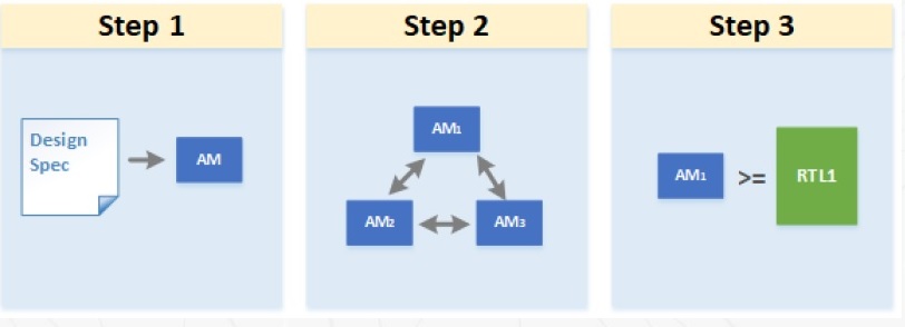
Prior to focusing on FV of RTL models, a unique facet of the recommended hybrid methodology is to create architectural models for each block, as depicted below.

The architectural models can be quite abstract, and thus small and easy to develop. The models only need to represent enough behavior to include key architectural features.
A major goal is to enable the verification team to develop and exercise the more complex interface and end-to-end FV assertions, and defer work on the properties self-contained within the block functionality. These architectural models are then connected to represent a broader scope of the overall hierarchy.
Although the resource invested in writing architectural model may delay RTL development, Scott highlighted that this FV approach expedites evaluation of complex, hard-to-find errors, such as for: addressing modes and address calculation; absence of deadlock in communication dependencies; verification of the order of commands; and, measurement of the latency of system operations.
Formal Verification of RTL
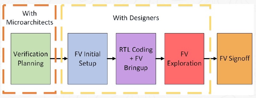
The development of additional FV assertions, assumptions, and covers expands in parallel with RTL model coding, with both the micro-architects and verification team contributing to the FV testbench.
The recommended project approach is for the micro-architects to focus initially on RTL interface functionality; these RTL “stubs” are immediately useful in FV (except for the end-to-end assertions). Subsequently, the baseline RTL is developed and exercised against a richer set of assertions and covers. And, the properties evaluated during the architectural modeling phase are re-used and exercised against the RTL.
As illustrated below, there is a specific “FV signoff” milestone for the block RTL.

The FV results are evaluated – no failing assertions are allowed, of course, and any assertions that are incomplete (bounded proven) are reviewed. Any incompletes are given specific focus by the dynamic verification testbench team – the results of a bounded search are commonly used as a starting point for deep state space simulation.
Promotion of FV Components to Higher Levels
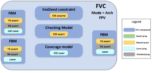
With a foundation in place for block-level FV signoff, Scott described how the FV testbench components are promoted to the next level of verification hierarchy, as illustrated below. The FV component is comprised of specific SystemVerilog modules, with assertions and assumptions partitioned accordingly. (An “FBM” is a formal bus model, focused on interface behavior properties.)

Each FV component has a mode parameter, which sets the configuration of assertions, assumptions, and covers. In ACTIVE mode, all assertions and covers are enabled; assumptions (in yellow) are used to constrain the property proof. When promoting an FV component, the PASSIVE mode is used – note that all assume properties are now regarded as assertions to be proven (green).
In short, any block model assumption on input ports need to be converted to assertions to verify (either formally or through dynamic simulation) at the next level of model integration.
Briefly, there is also an ARCH mode setting for each FV component, as depicted below:

If a high-level architectural model is integrated into a larger verification testbench, end-to-end and output assertions become FV assumptions (in yellow), while input assumptions are disabled (in grey).
Additional Formal Apps
Scott highlighted the additional tools that are still needed to complement the formal property verification methodology:
- inter-module connectivity checks (e.g., unused ports)
- clock domain crossing (CDC) checks for metastability interface design
- sequential equivalence checking, for implementation optimizations that introduce clock gating logic
- X-propagation checks
3rd Party IP Interface Verification
If the design integrates IP from an external source, a FV-focused testbench is a valuable resource investment to verify the interface behavior. Scott mentioned that end-to-end assertions that are developed to ensure the overall architectural spec correctly matches the 3rd party IP behavior have proven to be of considerable value. (Scott also noted that there are commercially-available FV testbenches for protocol compliance for industry-standard interfaces.)
Dynamic Verification
Although FV verification can accelerate bug finding, Scott reiterated that their verification team is focused on a hybrid methodology, employing DV for deep state bug hunting, and for functionality that is not well-suited for formal verification. Examples of this functionality include:
- workload-based measurements of system throughput and interface bandwidth
- power state transition management
- firmware and hardware co-simulation (or emulation)
- SerDes PHY training
Results
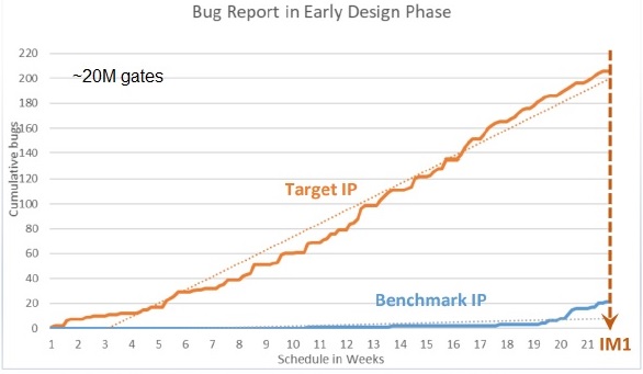
The planning, development, and application of FV components and integration in a verification testbench requires an investment in architecture, design and verification team resources. Scott presented the following bug rate detection graph as an indication of the benefits of the approach they have adopted.

The baseline is a comparable (~20M gate) IP design, where dynamic verification did not begin in earnest until the initial RTL integration milestone. The early emphasis on FV at the architectural level captured hundreds of bugs, quite a few related to incorrect and/or unclear definitions in the architectural spec (including 3rd party IP integration). These bugs would have taken much longer and more verification resource to uncover in a traditional DV-only verification flow.
Summary
Formal property verification has become an integral part of the initiative toward a shift-left methodology. Early FV planning and assertion development combined with a resource investment in architectural modeling helps identify bugs much earlier. A strategy for focusing on FV at lower levels of the design hierarchy, following by evaluation of constraints at higher levels of integration, will offer FV testbench reuse benefits. This is an improved method over lower-level dynamic verification testbench development that is commonly discarded as the design complexity progresses.
The best practices FV methodology recently presented by Intel at DVCON is definitely worth further investigation.
References
[1] IEEE Standard 1800 for SystemVerilog, https://ieeexplore.ieee.org/document/8299595
[2] Chen, Hao; Peverelle, Scott; et al, “Maximizing Formal ROI through Accelerated IP Verification Sign-off”, DVCON 2022, paper 1032.
Also read:
Intel Evolution of Transistor Innovation
The Intel Foundry Ecosystem Explained
Share this post via:


Comments
There are no comments yet.
You must register or log in to view/post comments.