Normalized image log-slope (NILS) is probably the single most essential metric for describing lithographic image quality. It is defined as the slope of the log of intensity, multiplied by the linewidth [1], NILS = d(log I)/dx * w = w/I dI/dx. Essentially, it gives the % change in width for a given % change in dose. This is particularly critical for EUV lithography, where stochastic variations in dose are naturally occurring.
A dark feature against a bright background has a higher NILS than a bright feature against a dark background. The reason is the intensity in the denominator is relatively much lower for the dark feature than the bright feature. For this case, the NILS is also made sufficiently high, e.g., > 2, with a sufficiently high mask bias, i.e., a dark feature size on the mask larger than 4x the targeted wafer dark feature size. However, if the dark feature on the mask is too large compared to the spacing between features, then there is too little light reaching the wafer. This means that a longer exposure time is needed to accumulate a sufficient number of photons absorbed. A way around this is to use an attenuated phase shift mask, or attPSM in abbreviation. The dark feature is actually partially transmitting light through the mask, and imparting a phase shift of 180 degrees. Both transmission (or reflectivity in the case of EUV) and phase are adjusted by the material and thickness of the dark feature on the mask.

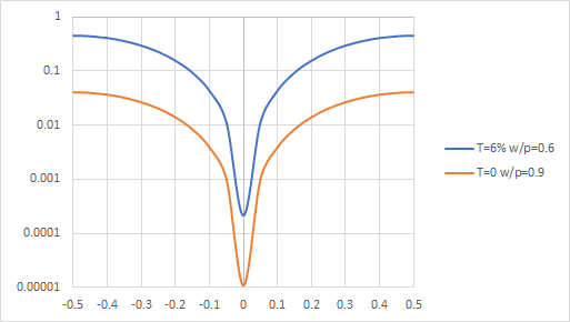
Figure 1. The same NILS requires much longer exposure with a binary (T=0) mask than a 6% attPSM. This is based on a 4-beam image of dark island feature (width w, pitch p) in an expected quadrupole illumination scenario.
In Figure 1, we see that with the same NILS, the log-slope curves are similar in shape, but the attPSM with less bias than the binary mask allows more light to get to the wafer, so that a long exposure is not needed.
With the advantage of using an attPSM made clear, let’s turn now to why EUV hasn’t implemented any yet. A fundamental difference between an EUV mask and a DUV mask is that while there is only single pass of light through the DUV mask, the EUV mask has two passes of light through the pattern layer, and in between passes, the light propagates through a multilayer, which tends to absorb more light at higher angles [2].

Figure 2. While a DUV mask (left) is treated as a thin pattern layer, an EUV mask (right) is treated as two pattern layers separated by an absorbing layer, i.e., the multilayer.
Consequently, the phase shift (also no longer targeted at 180 degrees, but over 200 degrees [2]) is distributed over multiple layers, and not easily tailored by adjusting one layer’s thickness. Moreover, the known candidate materials are hard to process with good control. Materials like ruthenium and molybdenum easily oxidize. A few nanometers change of thickness can add tens of degrees of phase shift [3]. The different individual wavelengths within the 13.2-13.8 nm range also have significantly different phase shifts as well as reflectivities from the multilayer [4]. Regardless of these complicating factors, designing attPSMs for EUV continues to be a topic of ongoing investigation [5].
References
[1] C. A. Mack, “Using the Normalized Image Log-Slope,” The Lithography Expert, Microlithography World, Winter 2001: http://lithoguru.com/scientist/litho_tutor/TUTOR32%20(Winter%2001).pdf
[2] C. van Lare, F. Timmermans, J. Finders, “Mask-absorber optimization: the next phase,” J. Micro/Nanolith. MEMS MOEMS 19, 024401 (2020).
[3] I. Lee et al., “Thin Half-tone Phase Shift Mask Stack for Extreme Ultraviolet Lithography,” https://www.euvlitho.com/2011/P19.pdf
[4] A. Erdmann et al., “Simulation of polychromatic effects in high NA EUV lithography,” Proc. SPIE 11854,1185405 (2021).
[5] A. Erdmann, H. Mesilhy, P. Evanschitzky, “Attenuated phase shift masks: a wild card resolution enhancement for extreme ultraviolet lithography?,” J. Micro/Nanopattern. Mater. Metrol. 21, 020901 (2022).
This article first appeared in LinkedIn Pulse as Phase-Shifting Masks for NILS Improvement – A Handicap For EUV?
Also Read:
Lithography Resolution Limits: The Point Spread Function
Sino Semicap Sanction Screws Snugged- SVB- Aftermath more important than event
Resolution vs. Die Size Tradeoff Due to EUV Pupil Rotation
KLAC- Weak Guide-2023 will “drift down”-Not just memory weak, China & logic too
Share this post via:


A Century of Miracles: From the FET’s Inception to the Horizons Ahead