The current leading edge of advanced lithography nodes (e.g., “7nm” or “1Z nm”) features pitches (center-center distances between lines) in the range of 30-40 nm. Whether EUV (13.5 nm wavelength) or ArF (193 nm wavelength) lithography is used, one thing for certain is that the minimum imaged pitch will be less than the wavelength divided by the numerical aperture of the corresponding wavelength tool (0.33 for EUV, 1.35 for ArF immersion).
1X Pitch
Under these conditions, the targeted minimum pitch, which will be labelled as “1X” here, is imaged as the interference of two beams, no more, no less. Furthermore, only certain illumination angles will allow this interference to occur; other angles will not produce any image at all, and only appear as unwanted background light.
2X Pitch
Commonly, a processor layout can also include 2X pitches, i.e., twice 1X, lines which are separated by twice the minimum distance. These naturally occur when design grids are used, with the grid spacing correlating to the minimum pitch. However, when 2X pitches are imaged with the same illumination as 1X pitches, there is not only a difference of image but also a difference of depth of focus. The reason is 2X pitches are imaged as the interference of three beams rather than two.
Figure 1. Two-beam interference for 1X pitch and three-beam interference for 2X pitch.
1X vs. 2X Depth of Focus
The difference of optical path lengths between the middle beam and the side beam is large for the three-beam case, while for the two-beam case, there is no middle beam and the two side beams have similar optical paths at the appropriate angle. Consequently, the depth of focus (DOF) is worse for the three-beam case compared to the two-beam case. On the other hand, at a non-optimum angle, even the two-beam interference will defocus poorly, for the same reason of different optical path lengths between the two beams (Figure 2).
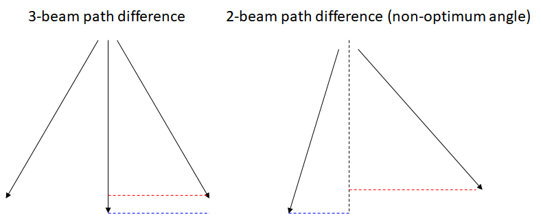
Figure 2. Different optical paths, indicated by the gap between the vertical positions of the different wavefronts in red and blue, for three-beam interference (left) and two-beam interference with non-optimum angle (right).
However, for the 2X pitch, it is still possible to find different illumination angles that result in close to the two-beam interference. These correspond to different source points in the pupil (Figure 3). The 2X pitch points have x angular coordinates which are half those of the optimum points for the 1X pitch, and at the same time, sufficiently high y angular coordinates to ensure that only two diffracted beams are captured within the numerical aperture.
Figure 3. Different source points in the pupil give rise to the desired two-beam interference patterns, for the 1X case (left: pitch = 0.88 wavelength/NA; right: pitch = 0.98 wavelength/NA) and the 2X case (left: pitch = 1.76 wavelength/NA; right: pitch = 1.96 wavelength/NA). Moreover, for the lower k1, the best DOF is a limited subset of all possible two-beam interference source points.
The different illumination conditions indicate the mutually exclusive defocus tolerance. A single exposure cannot offer the same focus windows to both 1X and 2X pitches.
Subresolution Assist Features (SRAFs)
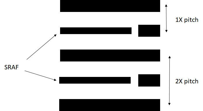
A widely suggested proposed solution [1] to accommodate both 1X and 2X pitches is to use subresolution assist features (SRAFs) on the 2X pitches to make them appear more similar to 1X features (Figure 4). This essentially suppresses the middle beam of the three beams, resulting in the growing of side lobes in between lines. Care must be taken, however, not to have these side lobes print. The 2X pitch isn’t changed, and the middle beam cannot be completely eliminated, so the focus window improvement will still be narrower than the 1X case. SRAFs would also be more vulnerable to stochastic effects due to their smaller sizes [2]. In situations where multiple patterning is already planned to be used to add or remove lines, the use of SRAFs to match 2X to 1X pitches would be unnecessary.
Figure 4. Subresolution assist features (SRAFs) make the 2X pitch look more like a 1X pitch. However, side lobe printing at the SRAF locations is a risk that cannot be neglected.
EUV Pupil Rotation Sensitivity
It has been reported [3,4] that the distribution of EUV illuminating source points rotates azimuthally about the optical axis at different points across the exposure slit, to a range of more than +/- 18 degrees (Figure 5); it is a natural outcome of using reflective ring-field optics [5]. As a result, illumination angles with best depth of focus are rotated to angles with inferior depth of focus. To avoid this undesired outcome, a large portion of the exposure slit would have to be excluded, resulting in effectively a much smaller exposure field width. To compensate, the scan across the wafer must stop at many more locations, reducing throughput substantially (Figure 6). Even worse, some chips are already very wide, almost taking up the entire maximum 26 mm field width. For these chips, the wide exposure width would have to be divided for multiple exposures with separately optimized illuminations. One patent from TSMC [6] even rotates different parts of the wide chip layout accordingly, in order to keep the single exposure.
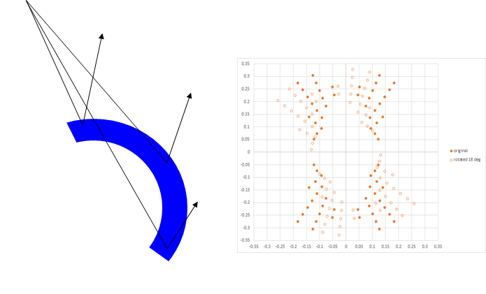 Figure 5. Pupil rotation across slit (~ +/-20 deg) does not preserve depth of focus at all slit locations, as the illumination source points are displaced from optimum locations.

Figure 6. Pupil rotation with a full field would suffer from illumination rotation (left); this can be mitigated with a smaller exposure field width (right), which requires more stopping time.
How It Is Dealt With
The 1X vs 2X pitch incompatibility for depth of focus can be handled in four different ways:
(1) Design rule restrictions: Exclude the 2X pitch as forbidden. This is by far the simplest approach. But it may be too restrictive.
(2) SRAFs: This has been implemented successfully for DUV lithography, with care taken to not print the SRAFs in the process. For EUV, though, stochastic effects are aggravated, and pupil rotation is not addressed.
(3) Multiple Patterning: Splitting out 1X and 2X pitches can occur as part of multipatterning.
(4) EUV pupil rotation: The EUV pupil rotation would either limit the exposure field or require pre-rotation of parts of the layout, to avoid multiple patterning otherwise.
References
[1] J. G. Garofalo et al., Proc. SPIE 2440, 302 (1995).
[2] https://www.linkedin.com/pulse/stochastic-printing-sub-resolution-assist-features-frederick-chen/
[3] R. Capelli et al., Proc. SPIE 9231, 923109 (2014).
[4] A. Garetto et al., J. Microlith/Nanolith. MEMS MOEMS 13, 043006 (2014).
[5] M. Antoni et al., Proc. SPIE 4146, 25 (2000).
[6] US Patent 9091930, assigned to TSMC.
This article first appeared in LinkedIn Pulse: A Forbidden Pitch Combination at Advanced Lithography Nodes
Share this post via:



TSMC vs Intel Foundry vs Samsung Foundry 2026