Designing DRAMs at Intel back in the 1970s I first learned about Soft Errors and the curious effect of higher failure rates of DRAM chips in Denver, Colorado with a higher altitude than Aloha, OR. With the rapid growth of FPGA-based designs in 2016, we are still asking the same questions about the reliability of our chips used for safety-critical applications like:
- Industrial IoT
- Automotive
- Space applications
Ideally our FPGA designs would use a methodology that supports error detection and correction to meet the uptime requirements of the system. My older 1998 Acura RL doesn’t offer much in terms of automatic driver assistance systems (ADAS), while the majority of new cars rolling off the assembly line now certainly do support ADAS features. As a consumer I really want my automobile to be safe and reliable, in spite of any glitches in the electronics. NASA has a budget running in the billions annually and their space-based craft need to operate in the harshest conditions of temperature range and cosmic radiation, so reliability remains a big requirement. Factories are quickly adopting industrial IoT approaches to become more competitive, so they need electronics that can be counted on to run with the highest uptime and fewest surprises, just think about the typical wafer fab and all of its equipment to keep the wafers moving without disruption.
Inside an FPGA
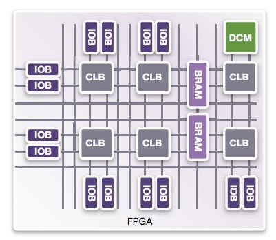
Typical FPGA chips have an architecture built on various specialized blocks, so let’s review what they are:
- Input, Output Buffers (IOB) – control data in and out of chip
- Digital Clock Module (DCM) – the clock network
- Configurable Logic Block (CLB) – implements digital logic
- Block RAM (BRAM) – memory primitives

Detecting and Fixing Errors
Each of the four FPGA blocks listed above need to be protected against the effects of errors caused by radiation or glitches. There are several approaches to consider for detection and correction:
- Logic redundancy and error correction with Triple Modular Redundancy (TMR)
- Logic duplication with software correction
- Memory scrubbing
Memories
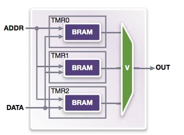
There are three typical approaches to protecting memories from errors and glitches:
- Error Correcting Code (ECC) memories to detect and fix Single Event Upsets (SEU)
- Using TMR to counter SEU
- Monitor RAM errors then scrub the memory to rewrite the correct data
Related blog – TMR approaches should vary by FPGA type
There is logic synthesis software from Synopsys called Synplify Premier that can automate all three of these methods into your FPGA designs.

TMR to counter SEU in memories
Both Xilinx and Alter devices are supported by Synplify Premier for these memory detection and correction types.
Finite State Machines (FSMs)
An FSM is often used for control logic in FPGAs and they have registers to store information like the present state, along with other logic and feedback. An error could occur in an FSM where the state register is affected, an output could flip to the wrong state, or the next state could be in error. Now you can create a safe FSM by detecting and correcting errors in the state register and then have logic that changes the FSM into correct operation. There are three methods for making a safe FSM:
- Using Hamming-3 codes for auto-detection and correction of single bit errors in the state register, fixing the error immediately
- A safe FSM that will auto-reset on detecting a single bit error, allowing correct operation to be reached
- Using a safe CASE FSM where the FSM recovers by special settings and using RTL guideline for defaults and other clauses
I/Os
These input/output blocks have clocked data and registers so are susceptible to radiation and glitches. The Premier tool has automation to create redundancy and include error checking.
Related blog – One FPGA synthesis flow for different IP types
Error Monitoring
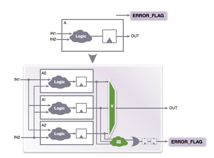
At the system level you may consider adding an error flag upon detecting that your FPGA logic has detected a failure. This flag can then be used by the system software to start some custom fixing or perhaps do memory scrubbing. You could gather statistics on how often a failure is occurring. Synplify Premier gives you options to add error flags using duplicate with compare, triple modular redundancy and safe FSMs. Here’s what TMR with an error flag capability looks like:

Summary
The pervasive use of FPGAs in our modern life is a given, so it makes sense to take an automated hardware approach for safety critical products that require highest reliability and functional safety. Designers of products used in automotive, industrial IoT and space should consider updating their manual design approaches with something that is more automated in order to be more thorough and productive. There’s a four page White Paper at Synopsys that has more details and you may download it online as a PDF file now.
Related blog – IoT or Smart Everything?
Share this post via:


Comments
There are no comments yet.
You must register or log in to view/post comments.