
As systems become increasingly complex across every field of science and engineering, the importance of computer simulation in design, analysis, and verification continues to increase over time. The traditional process in which a system is modeled and simulated in a single tool is called monolithic simulation. On the other hand, co-simulation is a technique in which multiple simulation tools exchange data at regular intervals, so that subsystems modeled in different tools can be simulated as one.
In many cases, complex designs cannot be modeled adequately through the lens of a single domain, as real-world systems are multidisciplinary in nature. For example, mechanical systems are driven by controller software, digital and analog electronics contend with non-ideal electromagnetic effects, and systems of all kinds release heat and must undergo thermal analysis. Multidisciplinary simulation tools exist and can be used effectively to address some of these requirements. However, in many cases, separate and specialized tools are required to model and simulate subsystems at sufficient depth or accuracy, introducing new challenges. These tools may be incompatible with each other, or it may be difficult to transfer models and simulation results across them. The process of compiling these results into a useful system-wide analysis can be time-consuming and error-prone.
This explains the necessity for co-simulation, in which simulation tools couple seamlessly to enable unified, system-wide simulation. To allow for co-simulation, tools must adhere to common standards and provide compatible interfaces. The Functional Mock-Up Interface (FMI) standard is currently the most widely adopted and promising standard for continuous, discrete, and hybrid co-simulation.
HyperLynx AMS (HL AMS) and PartQuest Explore are multidisciplinary analog/mixed-signal simulation tools from Siemens. HyperLynx AMS provides detailed mixed-signal analysis and is directly integrated with the PCB schematic capture and layout flow. PartQuest Explore is cloud-based and supports early architecture exploration and component selection. The recent implementation of FMI compatibility in PartQuest Explore and HyperLynx AMS opens a large range of co-simulation capabilities to these tools.
The Functional Mock-Up Interface Standard
The FMI standard is a free, tool-independent, open standard for the co-simulation of models between different simulation tools. FMI 2.0 is the most widely adopted version by industry tools as of 2025. Both HyperLynx AMS and PartQuest Explore adhere to FMI 2.0.
Development of the FMI standard is organized by the Modelica Association and is guided by the FMI Steering Committee, of which Siemens is a member. As of 2026, there are over 270 FMI-compatible tools spanning many different fields, disciplines, companies, and organizations. FMI-compatible Siemens tools include, but are not limited to, the following:
- HyperLynx AMS
- PartQuest Explore
- Siemens NX MCD
- Simcenter 3D
- Simcenter Amesim
- Simcenter FLOEFD
- Simcenter Flotherm
- Simcenter HEEDS
- Simcenter STAR-CCM+
- PSIM
- Twin Activate
FMI co-simulation is advantageous because its standardized and tool-independent nature means that a specialist in one tool does not need strong expertise in a different tool or discipline to perform co-simulation. When intellectual property and sensitive data must be protected, black-box models can be used to keep internal logic, equations, and algorithms opaque to the user.
FMI and FMUs
The FMI standard defines the interface between coupling simulation tools. An FMI co-simulation interface consists of the following:
- An application programming interface (API) that evaluates coupling equations and computations
- A functional mock-up unit (FMU), which is a containerized model that allows for deployment to a different tool or platform
- An interface description which contains static information about the FMU such as inputs, outputs, parameters, structure, attributes, and capability flags.
When two tools are coupled, one acts as the exporting tool and the other as the importing tool. Different subsystems are designed and modeled in each tool. The exporting tool containerizes and exports its model as an FMU, which is then imported by the importing tool and interfaced with its own model. In HyperLynx AMS and PartQuest Explore, the FMI interface is represented graphically by an FMU block with input and output ports that can be placed into the model schematics.
During co-simulation, the FMU and the importing model exchange data at regular, discrete points determined by the communication time-step. It is important to define an appropriate communication time-step to achieve the desired simulation accuracy while balancing the trade-off in simulation runtime. In general, the communication time-step does not need to be the same as the internal simulation time-steps set in the individual tools.
FMI Co-Simulation for Multi-Domain Analysis
A. Electromechanical co-simulation
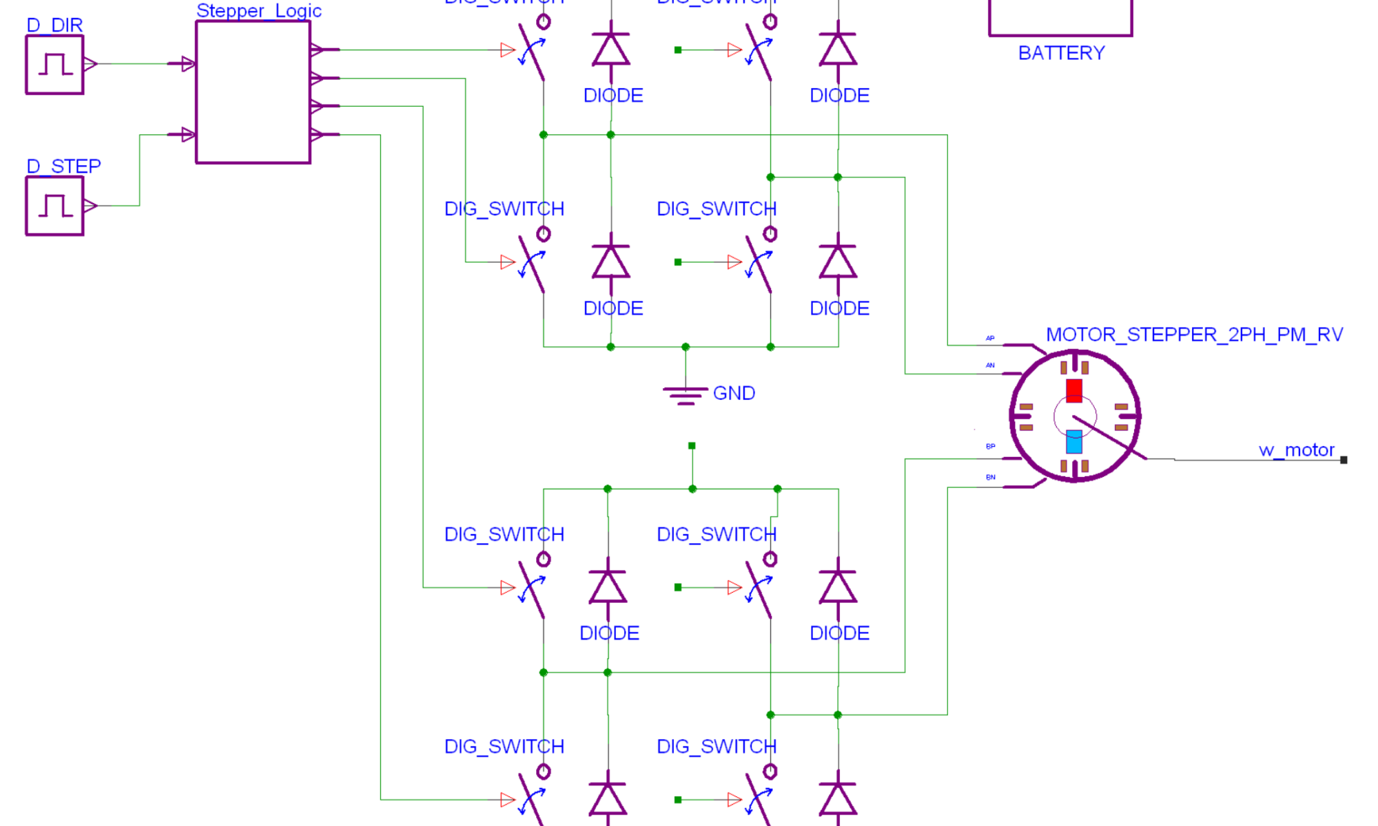
In this example, HL AMS exports an FMU to co-simulate with Simcenter Amesim, a multi-domain simulation tool with powerful mechanical and mechatronic simulation capabilities. An electrical subsystem, designed in Xpedition Designer and HL AMS, drives a stepper motor using a battery and power inverters controlled by digital switching signals (figure 1). The output of the stepper motor (w_motor) in HL AMS is connected to the mechanical model.

The mechanical subsystem is designed in Siemens Simcenter Amesim and is shown in figure 2. The input is received from the HL AMS motor model, and the model contains a gear reducer and a winch that attaches to a mass suspended on a rope. The outputs of the system are the rotational velocity of the gear shaft (w_rpm), and the distance between the mass and the ground (air_gap).

The stepper motor is controlled to repeatedly rotate six steps forward, then four steps back. In the mechanical model, this is expected to result in the mass being repeatedly raised six steps upwards and then lowered four steps downwards.
In HyperLynx AMS, the user defines the FMU and the nature of the data transmitted through each port. After the FMU is generated, an interface block is placed in the HL AMS schematic (figure 3).

The FMU is then imported into Amesim, and another interface block is placed and connected to the Amesim model (figure 4).

As mentioned before, it is important to set an appropriate co-simulation time step to balance simulation runtime and simulation accuracy. This example simulates over a five-second period, so a time step of 1 millisecond is chosen. If the results of a co‑simulation seem infeasible or incorrect, the value of the co-simulation time step is a good place to look when diagnosing the issue.
The subsystem models are now ready for co-simulation, and the results are shown in figure 5.

B. Control system co-simulation
One of the most common use cases for FMU co-simulation is in the design and simulation of control systems using tools such as Altair Twin Activate (a Siemens tool) and MathWorks Simulink. Twin Activate is a multidisciplinary system simulator with a graphical block-diagram modeler. In this example, a controller designed in Twin Activate is co-simulated with a power converter modeled in HyperLynx AMS.The power converter model is shown in figure 6. At the top-left of the schematic, there is an empty space in the feedback loop where a controller will be placed.

The controller is designed in Twin Activate environment (figure 7). From the Twin Activate environment, this controller model is exported as an FMU with one input port and one output port.

The FMU block is imported by HyperLynx AMS and placed in the feedback loop of the power converter model. The time period simulated is 30 milliseconds, so the 1 millisecond co-simulation time step used in the previous Amesim example would be too large for an accurate result. The time step is reduced to 1 microsecond in the parameters of the FMU block.
The co-simulation results are shown in figure 8. The load connected to the power converter is a variable resistive load that changes abruptly over time. The response to these disturbances can be observed in the output voltage waveform.

Note that the co-simulation can also be performed from the opposite side, with an FMU exported from HyperLynx AMS and imported by Twin Activate. The results are identical when this is done, assuming the parameters of the simulation remain unchanged.
C. Thermal co-simulation
Siemens Simcenter Flotherm is a computational fluid dynamics (CFD) simulation tool for electronics thermal management. Flotherm can export BCI-ROM models in VHDL-AMS format which can be used in PartQuest Explore simulations. It can also export FMUs, which allows PartQuest Explore and other FMI-compatible tools to directly interface with its powerful CFD solver.
This example demonstrates FMI co-simulation between PartQuest Explore and Flotherm to perform a thermal analysis of a smartphone board design. A 3D view of the smartphone board design is shown in the Flotherm environment (figure 9).

Figure 10 shows the locations of the relevant chips on this board. The topside of the board includes a processor with a flip-chip BGA, a PMIC chip for power management, and an RF chip for wireless transmission. The bottom-side of the board includes a flash memory chip, U2.

An FMU is generated by Flotherm and is imported into the PartQuest Explore design. The inputs of the FMU include the heat transfer coefficient, ambient temperature, and five sources that correspond with the power dissipated by each of the chips. The outputs correspond to temperatures collected by probes at various locations on and around the board.
An electrical subsystem is designed in PartQuest Explore to simulate the real-world use of a smartphone (figure 11). The simulation begins with the phone idling for 10 minutes. The smartphone user then streams a television episode for 25 minutes and plays an offline video game for 25 minutes afterwards. The current drawn by each chip is approximated by variable current sources that model behavior during each of the three usage states. For example, the RF chip dissipates more power during the streaming state but idles during the gaming state because the offline video game does not need wireless connectivity. Meanwhile, the processor dissipates more power while gaming than it does while streaming. The power dissipated by the PMIC chip is modeled as a small percentage of the total power dissipated by the other three chips.

Since the time period simulated is an hour long, a co-simulation time step must be chosen to maintain a reasonable runtime. The time step is set to 100 milliseconds. The co-simulation is performed, and the results are shown in figure 12. The transitions between idling, streaming, and gaming can be clearly seen at 600 seconds and 2100 seconds. Notice that the RF chip (blue waveform,) cools down when entering the gaming state at 2100 seconds, while the processor (red waveform) heats up. The outer case (black waveform) stabilizes at about 37 degrees Celsius while the user is gaming.

Conclusion
FMI co-simulation allows for more effective analysis of complex multidisciplinary systems. The strengths and specialized capabilities of different simulation tools can be combined and leveraged with greater ease. The tool-independent nature of the FMI standard, and the black-box model of functional mock-up units, allows for simulation tools to couple seamlessly while protecting sensitive information and intellectual property.
It is important to keep in mind that co-simulation functionalities are implemented differently in each FMI-compatible simulation tool. Co-simulation is a powerful design analysis option that often requires careful consideration for modeling and set up. If help is needed, users should consult documentation or contact support services for the tools in their co-simulation flow.
The full list of FMI-compatible tools can be found at https://fmi-standard.org/tools/. The FMI standard website also hosts educational literature and documentation, as well as tools for validating, testing, and debugging FMUs.
To learn more about FMI co-simulation in HyperLynx AMS, PartQuest Explore, and other Siemens simulation tools, download the white paper here.
Daniel Zhang, Siemens Digital Industries Software
Daniel Zhang has been with Siemens EDA since 2023 and is a Technical Marketing Engineer with the Electronic Board Systems division. He holds a Master of Science degree in electrical and computer engineering. He specializes in system simulation tools such as HyperLynx AMS and PartQuest Explore.
References
- Schweiger et al., “An empirical survey on co-simulation: promising standards, challenges, and research needs”, Simulation Modelling Practice and Theory, Volume 95, September 2019.
- Bertsch, E. Ahle, and U. Schulmeister, “The Functional Mockup Interface – seen from an industrial perspective”, Proceedings of the 10th International Modelica Conference, March 2014.
- “Functional Mock-up Interface for model exchange and co-simulation”, Modelica Association, July 2014.
- Bertsch, C. Gomes, and M. Palmieri, “FMI beginner’s tutorial”, 16th International Modelica and FMI conference, September 2025.
- Siemens DISW, “The Benefits of Model-based Engineering in Product Development – from PCB to Systems”, Siemens Digital Industries Software, 2020.
- Donnelly, “Introducing BCI ROM for electro-thermal design”, PartQuest Explore, Siemens Digital Industries Software, March 2021.
- Blackmore, “The future of thermal design – earlier electrothermal analysis”, Siemens Digital Industries Software, December 2020.
Also Read:
GPU-native mask rule checking eliminates the curvilinear mask rule check bottleneck
Engineering the Next Era of Semiconductor Innovation
Library Characterization gets a Boost from AI
Share this post via:


Comments
There are no comments yet.
You must register or log in to view/post comments.