Two central concepts have led to the growth of our ability to manage and implement larger and larger designs: hierarchy and higher levels of abstraction. Without these two approaches the enormous designs we are seeing in SOCs would not be possible. Hierarchy in particular allows the reuse of component blocks, such as CPU cores. This has been a major enabling element to SOC designs. Due to the very real clock rate ceiling for practical CPU implementation, the move to multiple parallel processors has been essential to increasing performance without running into power and bandwidth issues.
Back in the late 1990’s physical chip design was hierarchical, and it was Mentor that lead a revolution in leveraging hierarchy for DRC. Now, Mentor is a leader in the move to make DFT and ATPG hierarchical, taking special advantage of repeated blocks. They have moved test insertion and test operations themselves to the block level, unlocking many efficiencies and reducing overall complexity. Mentor’s Tessent Hierarchical ATPG Flow at the RTL level offers many advantages.
Mentor and ARM have published a reference flow showing how DFT and ATPG can be implemented at RTL in an SOC containing multiple Cortex-A75s. Fully one third of the reference flow introduction is documentation of the steps used in the flow. This provides useful technical information useful for implementation. The first part of the document discusses the approach and advantages of the flow.
For the purposes of the reference flow, which uses 4 instances of the A75, they implemented two levels of DFT: the wrapped A75 core and top-level logic. Once the A75 core is wrapped it can be placed multiple times in the SOC. The finished chip contains MBIST and 1149.1 boundary scan logic. Also included are on-chip clock controllers (OCC), Tessent TestKompress controllers (EDT) and the test access mechanism (TAP).
The flow starts with MBIST insertion in the A75 block, followed by EDT and OCC insertion, all at RTL. After this, block synthesis is performed as usual. Next is scan insertion and retargetable ATPG for the block. Within the A75 the Tessent MBIST can use the shared memory bus. Once the A75 is done with test, the reference flow moves on to the top-level logic.
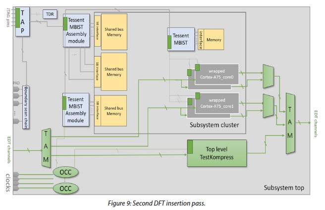
For the top level, boundary scan and MBIST are added first. A JTAG compatible TAP controller, Tessent boundary scan logic, an IJTAG-based Tesesnt MBIST assembly module for shared bus memories in the chip top level, and also regular Tessent MBIST for individual memories are added next. A second pass adds TestKompress logic and OCCs. The design also gets TAMs that can support multiple ATPG test modes. Each of the already wrapped A75s are included during the second pass.

So, what are the results? At the core level with 6,365 patterns for Stuck-at faults, they reach a coverage of 99.21%. For Transition faults, with 17,791 patterns, the coverage is 98.28%. In each case these numbers are just shy of the ‘ideal’ total for extest and intest coverage. Here are the top level ATPG results.

As I mentioned earlier, this is a detailed step by step description of the flow and includes actual annotated command descriptions for the process. This documentation shows the value of the partnership between ARM and Mentor and provides useful insight into the actual flow and its results. For users wishing to take this to the next level, the full reference flow package available from Mentor includes everything needed to implement this flow, including scripts, interfaces and documentation. To get started I’d suggest reading the overview from the Mentor website.
Share this post via:


Comments
There are no comments yet.
You must register or log in to view/post comments.