The diamond jewelry industry encourages customers to focus on the 4C’s — cut, clarity, color, and carats. At the recent PCB Forum conducted by Mentor (a Siemens business) in Santa Clara, I learned that current system design flows also require an emphasis on the 4C’s — collaboration, concurrency, consistency, and acloud environment. These capabilities need to span schematic design, constraint management, and physical PCB design and layout.
The complexity of current products requires attention to a plethora of details, to address the many optimization criteria:
- cost (area, layer stackups)
- routability
- minimization of high-frequency signal reflections and losses
- (differential pair and bus) signal topolopy matching
- manufacturability
- system thermal/EMI/mechanical packaging constraint (Look for another article shortly from the PCB Forum on MCAD-ECAD collaboration.)
The tasks of schematic design and physical implementation to achieve the goals above are tightly interdependent.
Collaboration among Applications
The conventional waterfall method for PCB development proceeds in a sequential manner — i.e., schematics and constraints are tossed “over the wall” to the physical design engineers to complete the implementation. This process simply does not address the demands of current PCB projects — a platform that enables an interactive, iterative, incremental flow is needed to support schematic and physical implementation designers collaborating in real-time.
Proposed edits to components or constraints need to be communicated among the design team for review and approve/reject decisions. A robust notification system is required, to indicate an update in one application that impacts other dependencies.
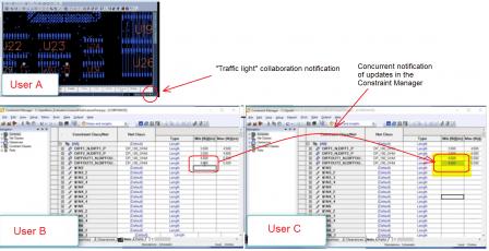
Mentor’s Xpedition platform utilizes a “traffic light” indicator in each application, to highlight that a change has been made in another interdependent application — greenis in sync, amber indicates an update in another application has been recorded. The Project Integrator pulldown is used to provide detailed information of the specific change for review. Designers are collaborating across applications in real-time.
The figure above illustrates three users working on the same project database — two in the constraint manager, and one in physical layout. An update in the constraint manager is shared concurrently with the other user, while the physical layout session is notified of the update.
Concurrent Design within an Application
Another reality of current projects is that the optimization of a complex system will involve the skills of all team members, leveraging specific expertise. The PCB development platform needs to readily support concurrent design among team members working on different areas of the design within the same application.
There are brute-force “partition, work independently, and re-assemble” approaches to concurrent design. Yet, designers require real-time visibility to the full design model — a true concurrent platform enables the full design data to be accessible.
Mentor’s Xpedition platform enables a fully concurrent set of users working in the same application on the full project database.
Consistency is a MUST
A development platform that enables collaborative, concurrent design MUST ensure the consistency of the “live” data being updated by the various team members. Xpedition maintains a single, consistent database model. For example, schematic sheets being edited are locked for others to edit until the sheet is closed — however, as schematic objects are modified, updates are visible in real-time to users viewing the schematic set. Design constraints being inserted/edited are locked until the edit is complete — the specific user performing the edit is displayed to other users viewing the constraint set. Once the edit is complete, updated objects are then highlighted to other users. For multiple designers working concurrently on a board layout, Xpedition provides isolation through real-time “force fields” representing the active neighborhoods in which separate designers are working, visible to all clients.
The figure above illustrates multiple concurrent layout users, with the force field identifying an active edit area of one user, and thus, a keepout for the others.
At the PCB Forum, Mentor provided a live demo of the unique features of these Xpedition product platform for concurrent, collaborative PCB design. It was one of those “Wow, that’s incredibly productive!” design methodology demonstrations.
A central Xpedition server manages the project data and concurrent access by multiple (up to 16) design clients. The demo highlighted how collaborative updates are dynamically reported to another application’s client using the traffic light indicator — e.g., the layout designer receives an amber notification when there is a component change in a schematic or an update to a property=value assignment in the constraint manager. The demo also highlighted how multiple clients work concurrently in the same application, with the appropriate locking of data objects.
Xpedition’s collaborative, concurrent environment supports both a lightweight data management/notification system, and a full enterprise-level DM application, which includes full user privilege and authentication controls, notification and signoff policies, and version/configuration management support. In either the Xpedition lightweight or xDM-based data management mode, client sessions are independent — the individual design workspaces are separate, supporting unique user preferences.
In addition to the use of a site-based server, the Xpedition collaboration features support a cloud-based project database.
Mentor’s Xpedition design platform addresses the 4C’s required by large, complex systems, enabling a Collaborative (multiple, dependent applications), Concurrent (same application) environment, with data management features ensuring Consistency, across a site or Cloud-based project database. The transition from a waterfall process to a more flexible methodology offers substantial project productivity benefits.
For more information on Xpedition’s design platform and collaboration features, please follow these links:
additional Mentor PCB Forum locations/dates
Concurrent Engineering landing page (with multiple video demonstrations)
Collaborative Management of Design Constraints blog
Concurrent Schematic Design blog
Real-time Concurrent PCB Layout blog
-chipguy
Share this post via:


Comments
0 Replies to “The 4C’s of PCB Design”
You must register or log in to view/post comments.