I met with Jeff Wilson, Product Marketing Manager at Mentor in the Calibre product group to learn more about Smart Fill versus Dummy Fill for DFM flows. Jeff works in the Wilsonville, Oregon office and we first meet at Silicon Compilers back in the 1990’s.
Dummy Fill

This diagram shows an IC layout layer on the left as originally designed, then on the right we see the same layout with extra square polygons added in order to fill in the blank space. Source: AMD
IC layouts use multiple layers like metal, poly, diffusion, via, etc. to interconnect transistors. The fab engineers know that if you can make each layer with a certain density that the yield will be acceptable. Dummy fill as shown above has worked OK for many nodes however the yield at 65nm and smaller nodes for digital designs requires a new approach in order to keep yields high.
The dummy fill helps make each layer more planar, and so there are DFM rules that need to be followed.
Q: How popular is Calibre with the dummy fill approach?
A: Calibre serves about 80% of the dummy fill market now.
Q: Is fill only used on metal layers?
A: No, actually all layers can benefit from fill techniques.
Smart Fill
Q: Why do we need to change from dummy fill?
A: The DFM rules for digital and analog designs have become more complex and the dummy fill approach just isn’t adequate to meet the rules. With dummy fill you are going to have too many violations that require manual edits, this takes up precious time on your project.

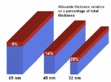
The percentage of total thickness variation has increased at each node, making CMP variation a critical issue requiring analysis. Source: ITRS
Q: What is the new approach with Smart Fill?
A: It’s DFM analysis concurrent during the fill process, so that the layout is more correct by construction.
Q: Do I need manual edits to my layout after running Smart Fill?
A: Our goal is to have zero edits after Smart Fill.
Q: At what node do I have to consider using Smart Fill?
A: Our experience with foundries and IDMs is that at 65nm and below for digital designs, and 250nm and below for analog designs will directly benefit from Smart Fill.
Q: What other issues are there to be DFM compliant with fill?
A: The size of the IC layout database needs to be reasonable and the run times kept short.

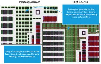
Dummy Fill on left, SmartFill on right. Source: AMD
Q: When I use the Calibre Smart Fill, do I need to learn to write new rules?
A: No, our approach has you write fewer rules.
Q: What kind of run time improvements could I see with Smart Fill?
A: One customer reported that dummy fill ran in 22 hours while Smart Fill ran in 40 minutes.
Q: What is the Mentor product name for Smart Fill?
A: We call it SmartFill and it’s part of Calibre Yield Enhancer.
Q: What other areas does YieldEnhancer automate?
A: Litho, CMP, ECD, Stress and RTA.]
Q: What about my critical timing nets?
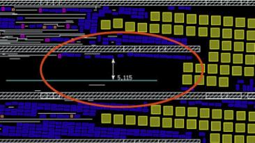
A: SmartFill can read in a list of your critical nets and then avoid interfering with their performance by using spacing.

Source: Mentor Graphics
Q: Who would use a tool like SmartFill?
A: Foundries, IDMs and Fabless design companies that want a technology advantage.
Q: What layout databases does SmartFill support?
A: Milkyway (SNPS), OA (Cadence), LEF/DEF (Cadence), Oasis.
Q: How do you keep run times low?
A: Through Cell-based fill (more than a single shape), it helps keep the file size and run times more reasonable.
Summary
To keep yield levels acceptable there are new DFM rules that affect how fill is created. The old approach of dummy fill has given way to Smart Fill which uses a concurrent analysis approach during fill to assure that DFM rules are not violated.


Comments
0 Replies to “Smart Fill Replaces Dummy Fill Approach in a DFM Flow”
You must register or log in to view/post comments.