Introduction
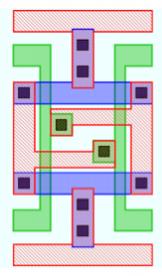
IC designs go through a layout process and then a verification of that layout to determine if the layout layer width and spacing rules conform to a set of manufacturing design rules. Adhering to the layout rules will ensure that your chip has acceptable yields.
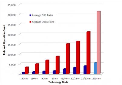
At the 28nm node a typical DRC (Design Rule Check) deck will have about 2,500 rules which requires that a fab engineer writes about 15,000 lines to check those rules.
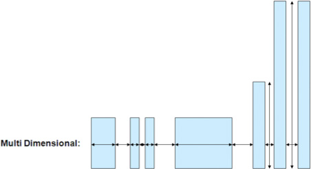
In the early days of IC design these layout rules were basically a minimum width and spacing number for each layer of your design.

It’s not so simple today because we have layout rules where the width and spacing depend upon the length of the net and also upon adjacent interconnect.
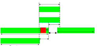
Even when your IC layout is DRC clean there can be locations on the layout that will cause unintended yield loss.

If you only knew ahead of time where these areas are located then you could change the layout in order to improve your yield.
What the Foundry Knows
The good news is that every foundry knows through silicon experience what many of these yield limiting layouts look like. The issue is how to describe these complex layouts because using text-based rules takes a lot of expertise to create and much time to verify correctness.
Graphical DRC versus Text-based DRC
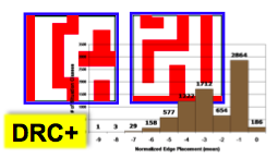
DRC decks have traditionally been written using a text editor, just like software code. A new approach has been added for defining layout rules using graphical patterns instead of writing rules. This new approach has been named DRC+ and Globalfoundries has defined a set of layout patterns that limit yield.
Calibre Pattern Matching
 I met with Michael White, Product Marketing Manager at Mentor Graphics to learn more about how pattern matching has been added to the Calibre product line.
Q: Who would use this new DRC+ graphical approach?
A: Mostly the foundry, or IDM would use it to find yield detractors. Even fab lite companies can create their own set of yield detractors.
Q: Who defines the patterns?
A: Anyone involved with yield analysis would create these patterns.
Q: When I graphically define a pattern can I then see the rules that it writes?
A: No, those rules are encrypted and used by Calibre internally.
Q: Any pattern could be rotated or flipped, how do you handle that?
A: Calibre finds all 8 orientations of a defined pattern automatically.
Q: If I already know how to use Calibre, then how much do I have to learn about DRC+?
A: You would run Calibre like before and view results with RVE (Results Viewing Environment). You can learn the graphical tool to enter new patterns and that takes a day.
Q: Can I mix DRC+, equations and rules?
A: Yes, they can all be used on your IC layouts.
Q: Can my patterns find all-angle layouts?
A: Today we support Manhattan patterns although it’s technically feasible to add all-angle support.
Q: Could you read an existing SVRF (Standard Verification Rule Format) deck and create a graphical version of it?
A: That’s not really practical.
Q: What kind of time savings is there if I use graphical pattern matching to create my rules?
A: Toshiba reports that it takes 36X less time to create a golden SVRF deck using this graphical approach.
Q: About how much time does it take to learn how to use graphical rules?
A: Customers take about one to two weeks elapsed time to come up to speed with this approach.
Q: Do the foundries protect their graphical rules?
A: Yes, they use encryption in our tools to protect their rules.
Q: Are their limitations to the number of graphical rules than can be run?
A: We see engineers using millions of patterns with acceptable run times.
Q: When a process node goes from 40nm to 28nm, then how many patterns are there?
A: About 10X new patterns for each successive node.
Q: When Calibre finds a pattern match, then how can the violation be fixed?
A: Within our P&R flow we do automated fixing of DRC violations.
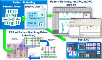
Q: What are the benefits of using Calibre for pattern matching?
A: Fast speed, a golden flow with DRC+ added, single deck with both DRC and DRC+, same Calibre RVE for debug, fits into major IC tool flows, supports hierarchy.
Q: Globalfoundries supports DRC+, what about other foundries?
A: Stay tuned.
Summary
Text-based DRC has been used for decades, however the addition of DRC+ will significantly reduce the amount of time that it takes to create a golden deck of layout design rules. Globalfoundries and Mentor have cooperated to add DRC+ to Calibre and serve IC customers at the 28nm node.


Comments
There are no comments yet.
You must register or log in to view/post comments.