I first heard about High Level Synthesis (HLS) while working in EDA at Viewlogic back in the 1990s, and have kept watch on the trends over the past decades. Earlier this year Siemens EDA hosted a two day event, having speakers from well-known companies share their experiences about using HLS and High Level Verification (HLV) in their semiconductor products. I’ll recap the top points from each speaker in this blog.
Stuart Clubb from Siemens EDA kicked off the two day event, and he explained how general purpose CPUs have struggled to meet compute demands, RTL design productivity is stalling, and that RTL verification costs are only growing. HLS helps by reducing both simulation and verification times, allowing for more architectural exploration, and enables new domain-specific processors and accelerators to handle new workloads more efficiently. The tool at Siemens EDA for HLS and HLV is called Catapult.
Catapult
With the Catapult tool designers model at a higher-level than RTL with C++, SystemC or MatchLib, which then produces RTL code for traditional logic synthesis tools. Your HLS source code can be targeted to an ASIC, FPGA or even eFPGA. There’s even a power analysis flow supported with the PowerPro add-on.
NXP
This company has 31,000 people, producing revenues of $11.06 billion in 2021, located across 30 countries and Reinhold Schmidt talked about their secure car access group of 11 engineers. Their product included an IEEE 802.15.4z compliant IR-UWB transceiver, ARM Cortex M33, and a DSP; they started with a 40nm process then migrated to a 28nm process, and their device operates on a coin cell battery.
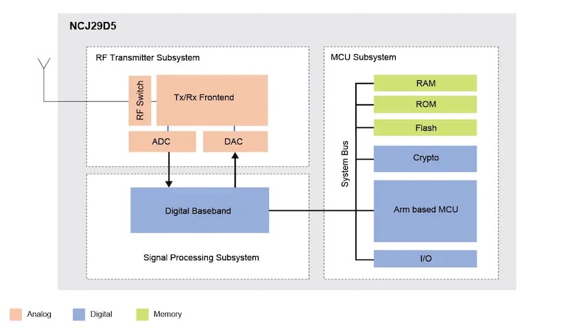
Modeling was done in Matlab, C++ and SystemC. MatchLib, a SystemC/C++ library was also used. PowerPro was used for power optimization and estimation. Results on an IIR DC notch filter showed that HLS had an area reduction of about 40%, compared to handwritten RTL.
They plan to integrate HLS further into their infrastructure, and investigate using HLV. It’s a challenge to get their RTL-centric engineers to think in terms of algorithms, and for SW engineers to think about hardware descriptions.
Google, VCU
Video traffic takes up to 80% of the Internet, so Google has focused their HW development on a Video Coding Unit (VCU). Aki Kuusela presented the history of video compression: H.264, VP9, AV1, AV2. Video transcoding follows a process from creator to viewer:

Google developed their own chips for this video transcoding task to get a proper implementation of H.264 and VP9, optimized for datacenter workload, so an HLS design approach allowed them to do this quickly. With a Google VCU a creator can upload a 1080p 30 fps video at 20 Mbps, then a viewer can watch it at 1080p 30fps using only 4 Mbps.
The VCU ASIC block diagram shows how all the IP blocks are connected to a NOC internally.
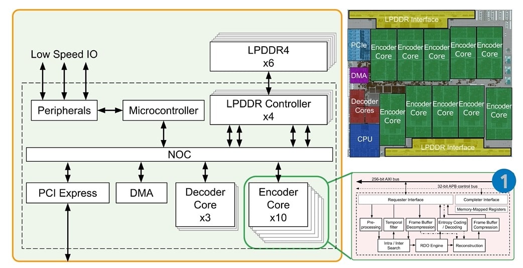
The VCU ASIC goes onto a board and rack, then it’s built up into a cluster. Google engineers have been using HLS for about 10 years now, and the methodology allows SW/HW co-design, plus fast design iteration. Catapult converts their C++ to Verilog RTL, and an in-house tool called Taffel is used for block integration, verification and visualization.
HLS design style worked well for data-centric blocks, state machines and arbiters. With C++ there was a single source of truth, and there were bit-exact results between model and RTL, using 5 to 10X less code compared to RTL coding.
NVIDIA Research
Nate Pickney and Rangharajan Venkatesan started out with four research areas that HLS has been used in their group: RC18: Inference chip, Simba: Deep-learning Inference with chiplet-based architecture, MAGNET: A Modular Accelerator Generator for neural networks, IPA: Floorplan-Aware SystemC Interconnect Performance Modeling.
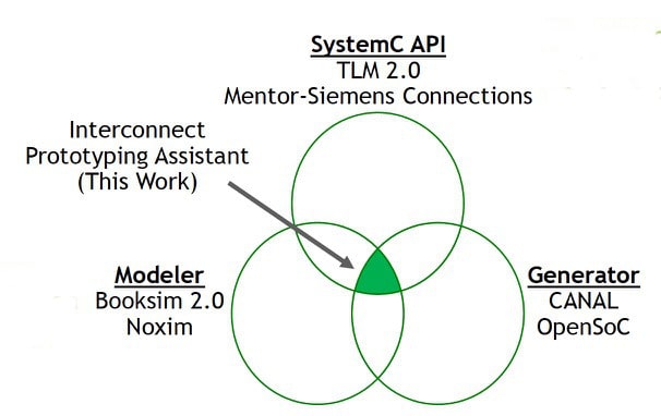
The motivation for IPA – Interconnect Prototyping Assistant, was to abstract and automate interconnects within a SystemC codebase. You use IPA’s SystemC API for magic message passing, SystemC simulation for modeling, and through HLS for RTL generation. IPA was originally developed by NVIDIA, and now is maintained by Siemens EDA.
The SoC design flow between HLS and RTL, including exploration and implementation is shown below:
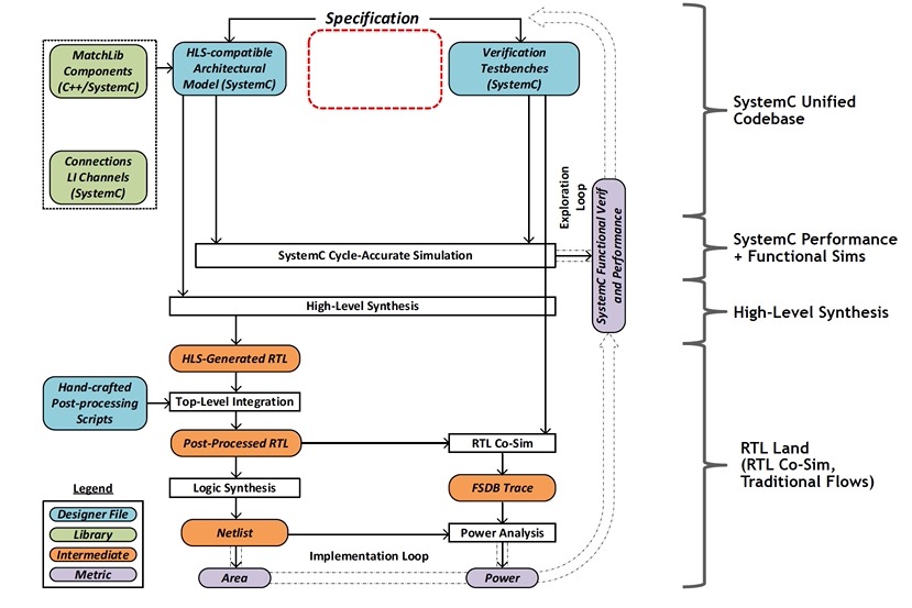
Adding IPA into this flow shows how exploration times can be reduced to 10 minutes, while implementation times are just 6 hours.
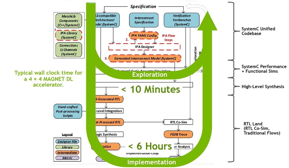
For the 4×4 MAGNET DL accelerator example the first step was to write a unified SystemC model, make an initial run of the IPA tool, update the interconnect, and then revise the microarchitecture. Experiments from this analysis compared directly-connected links, centralized crossbar, and uniform mesh (NOC). Each experiment using IPA took only minutes of design effort, instead of weeks required without IPA.
IPA info is open-source, learn more here.
NVIDIA, Video Codecs
Hai Lin described how their design and verification flow follows several steps:
- HLS design electronic spec
- HLS design lint check
- Efficient Catapult synthesis
- Design quality tracking
- Power optimization, PowerPro
- Block-level clock gating
- HLS vs RTL coherence checking
- Automatic testbench generation
- Catapult Code Coverage (CCOV) coverpoint insertions
Their video codec group switched from an RTL flow to Catapult HLS and saw a reduction in coding effort, reduced number of bugs, and shortened simulation runtimes. Automation now handled pipelining, parallelization, interface logic, idle signal generation and more. RTL clock gating is automated with PowerPro. Finally, the HLS methodology integrates code and functional coverage at the C++ design source-code level.
STMicroelectronics
Engineers at ST have 10 years of HLS experience using Catapult on products like set-top boxes, imaging and communication systems, and now are using HLS for products like: sensors, MEMS actuators – ASICs for MEMS mirror drivers, and analog products.
An Infrared Smart Sensor project used HLS, and a neural network was trained from a set of data coming from a sensor in real life situations.

With Catapult they were able to explore neural networks with various arithmetic formats, then compare the area, memory and accuracy of results. The time for HLS design in Catapult, data analysis, testbench and modeling was only 5 person-weeks.
A second HLS design project was for a Qi-compliant ASK demodulator. They were able to explore the design space by comparing demodulators with various architectures, then measure the area and slack time numbers:
- Fully rolled
- Partial rolled 8 cycles
- Partial rolled 4 cycles
- Partial rolled 2 cycles
- Unrolled
The third example shared was for a contactless infrared sensor with embedded processing. Three HW blocks for temperature compensation formulas were modeled in HLS.

The generated RTL from each block was run through logic synthesis and the area numbers were compared for a variety of architectures. Latency times were also estimated in Catapult to help choose the best architecture.
NASA JPL
FPGA engineer Ashot Hambardzumyan from NASA JPL compared using C++ and SystemC for the Harris Corner Detector. The main algorithm computes the Dx and Dy derivatives of an image, then computes a Harris response score at each pixel, finally applying a non-maximum suppression to the score.
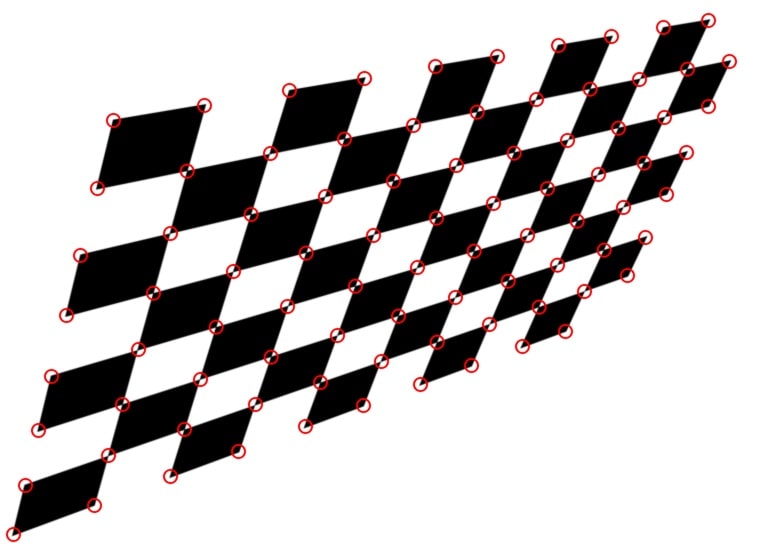
They modeled this as a DSP process, and the HLS architecture was modeled as a Kahn Process. Comparisons were made between using C++, SystemC and SystemVerilog approaches:

To verify each of these languages an image was used and the simulation time per frame was measured, and the SystemVerilog implementation required 3 minutes per frame, SystemC took only 5 seconds, and C++ was the fastest at only 0.3 seconds per frame.
Design and verification times for HLS were shorter than with RTL methodology. Basic training for using C++ was shorter at 2 weeks, versus SystemC at 4 weeks. The Harris Corner Detector algorithm took just 4 weeks using C++, compared to 6 weeks with SystemC.
Viosoft
The final presentation talked about 5G and the challenges of the physical layer (L1), where complex math is used in communication with algorithms like Channel Estimation, Modulation, Demodulation and Forward Error Correction.
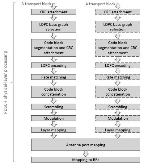
HLS was applied to L1 functions written in C++, then a comparison was made on the runtime for a CRC in three implementations:
- X86 XEON CPU 2.3GHz – 608, 423ns
- RISC-V QEMU CPU 2.3GHz – 4,895,104ns
- Catapult – 300ns
Another comparison was between an RTL flow versus Catapults flow for maximum clock frequency, and it showed that HLS results from Catapult were 2X higher clock frequency than RTL. Resource utilization in Intel FPGA devices showed that RTL from Catapult was comparable to manual RTL for logic utilization, total thermal power dissipation and static thermal power dissipation.
Viosoft prefers the single source implementation of HLS, as HW/SW can be partitioned easier, design trade-offs can be explored, performance can be estimated, and time to market shortened.
Summary
HLS and HLV are growing trends and I expect to see continued adoption across a widening list of application areas. Higher levels of abstraction have benefits like fewer lines of source code, quicker times for simulation, faster verification, all leaving more time for architectural exploration. RTL coding isn’t disappearing, it’s just being made more efficient with HLS automation.
There’s even HLS open source IP at Github to help get you started quicker. The Catapult tool comes with reference examples across different applications to speed learning. You’ll even find YouTube tutorials on using HLS in Catapult. The HLS Bluebook is another way to learn this methodology.
View the two day event archive here, about 8 hours of video.
Related Blogs
- AI Hardware Summit, Report #2: Lowering Power at the Edge with HLS
- Mentor Highlights HLS Customer Use in Automotive Applications
- Computer Vision Design with HLS
- Designing an SoC for 3D TV Without using the Funny Glasses


Comments
There are no comments yet.
You must register or log in to view/post comments.