I love to read articles about autonomous vehicles and the eventual goal of reaching level 5, Full Automation, mostly because of the daunting engineering challenges in achieving this feat and all of the technology used in the process. The auto industry already has a defined safety requirements standard called ISO 26262, and one of the questions that must be answered as part of the safety architecture is, “Do random failures violate any safety requirement?”
IC designers and test engineers have been aware of random failures in their semiconductor chips ever since the beginning, so over the decades have developed Design For Test (DFT) techniques like full scan design, and then adding tools like Automatic Test Pattern Generation (ATPG) to stimulate a fault, and then propagate that fault to an observable output pin. For automotive safety verification the approach is to:
- Inject a random fault
- Propagate the fault
- Check if safety mechanisms catch the fault
- Classify the fault
- Generate safety metrics
Siemens EDA has been in the DFT business for decades now, and they have extended that experience into the ISO 26262 realm, so I read a white paper from Jacob Wiltgen for a deep dive into the concept of fault campaigns.
Huge Number of Fault States
A simple two input logic gate can have three fault injection sites, but then consider that a modern SoC likely has a million+ gates, and that fault models can be both stuck-at and transient faults, so that’s a large fault state space.
The Automotive Safety Integrity Level (ASIL) has defined levels A through D, where D is the highest, and fault injection is highly recommended to meet ISO26262 requirements.
Functional Simulators
Every design engineer has easy access to a functional simulator, and for small blocks, sure, you could manually choose to inject faults, then verify the effects of that fault, but it would be too time consuming, so not viable.
Fault Injection Platform
Beyond functional simulators, there are now four helpful methods to inject faults and analyze the results:
- Formal Analysis
- Fault Simulator
- Fault HW Emulator
- Fault Prototype Board
With Formal Analysis you get the benefits of an exhaustive approach on smaller blocks where a fault classification proof is needed, while not requiring a test bench, but you need some formal experience.
For higher capacity than Formal Analysis consider using a Fault Simulator, and it does require a test bench where the efficiency depends on how good your stimulus is.
The highest capacity is achieved with a Fault Emulation method, and you can run software test libraries too.
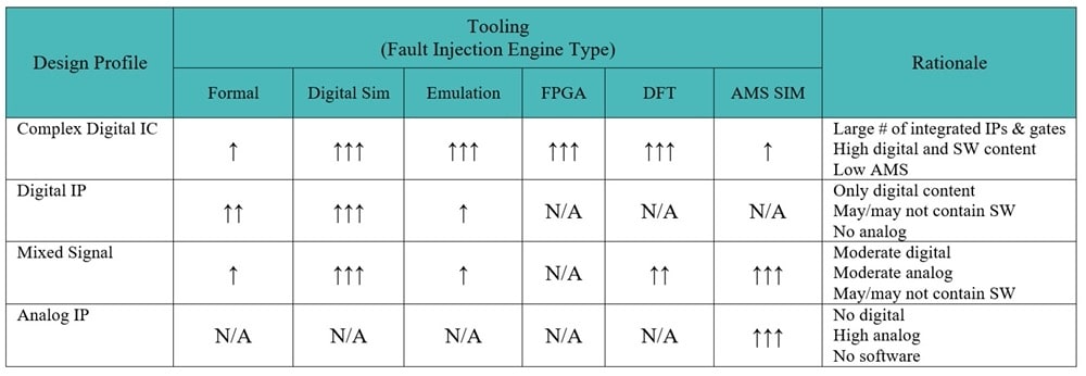
OK, we have these four distinct ways of doing fault injection, but how do I create the shortest fault campaign? It all starts with a written plan, detailing which approach will be applied to each block or module in a system, the total number of faults to be tested, etc. Consider using the following table to help you sort out the different Design Profiles of your system: Digital IC, Digital IP, Mixed Signal, Analog IP.
A second way to decide which tool to use for fault injection is by the Safety Feature: Digital HW, Software, LBIST/MBIST, Analog HW.
Fault Injection Methodology
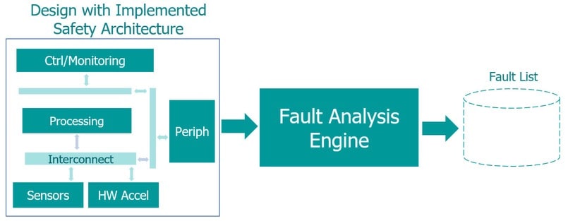
Start with your fault list generation, then run the fault injection tool, and finally the work product is generated as a Failure Modes, Effects and Diagnostic Analysis (FMEDA) report. A FMEDA will describe the failure modes, and safety metrics calculated using fault classifications spotted during the fault injection.
Fault List Generation
You determine if each fault in the fault list is safety critical or not. The flow for creating the fault list with the chosen safety architecture is:
Fault Injection
When a fault is injected and propagated, can we see the effects and does that infringe a safety goal or a safety requirement? Can the fault be detected by some safety mechanism?
A fault that infringes a safety goal or requirement are called Observed, while faults that can be detected by some safety mechanism are called Detected, so we get four fault classifications:
Each of the four injection methods are used, then the results get merged into a single list of fault classifications.
Work Product Generation
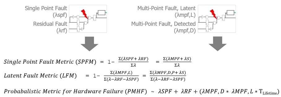
In the ISO 26262 standard there are three safety metrics that need to be calculated for your safety architecture:
- Single Point Fault Metric (SPFM)
- Latent Fault Metric (LFM)
- Probabilistic Metric for Hardware Failure (PMHF)
Equations for each:
The five FMEDA safety metrics are:
- Failure In Time (FIT)
- Single Point Fault Metric (SPFM)
- Latent Fault Metric (LFM)
- Probabilistic Metric for Hardware Failure (PMHF)
- Diagnostic Coverage (DC)
Summary
The safety architecture and ISO 26262 requirements for preventing random failures from becoming safety violations is a tough problem to solve, yet it can be done with the multi-prong approach developed by Siemens EDA over the years. Yes, there were lots of acronyms introduced in this blog, and the complete 14 page White Paper has even more details to bring you up to speed on designing and verifying automotive ICs that conform to safety standards.
Related Blogs
- Siemens EDA Updates, Completes Its Hardware-Assisted Verification Portfolio
- Observation Scan Solves ISO 26262 In-System Test Issues
- Automotive SoCs Need Reset Domain Crossing Checks
- Mentor Offers Next Generation DFT with Streaming Scan Network


Comments
There are no comments yet.
You must register or log in to view/post comments.