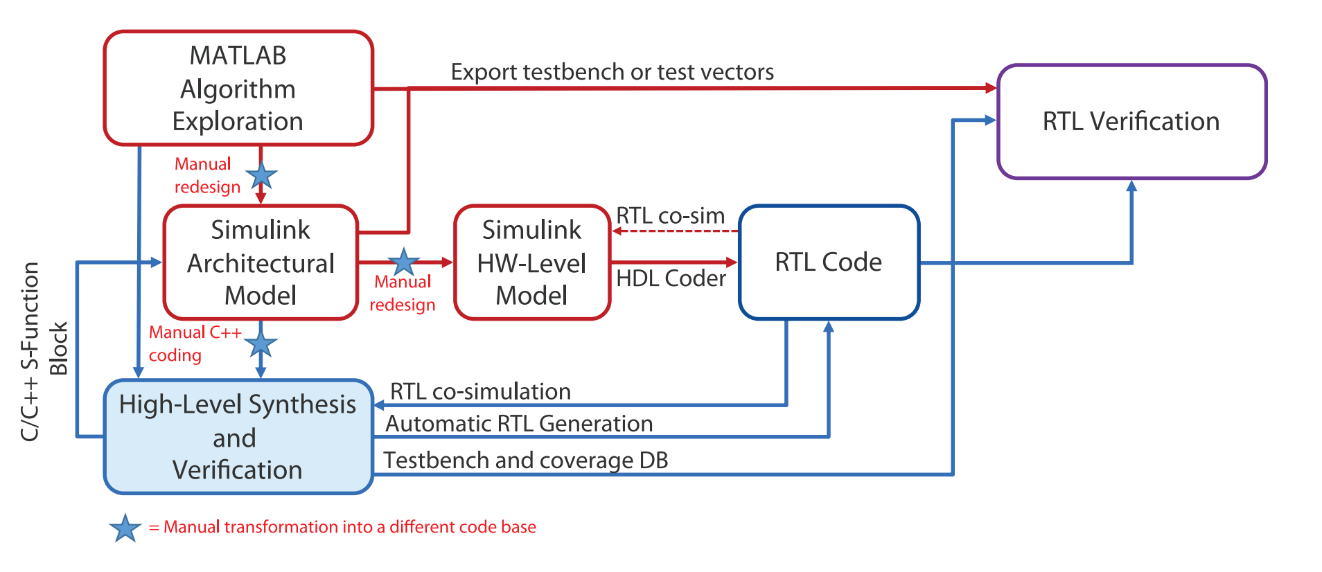
It hard to imagine design of a complex signal processing or computer vision application starting somewhere other than in MATLAB. Prove out the algorithm in MATLAB, then re-model in Simulink, to move closer to hardware. First probably an architectural model, using MATLAB library functions to prove out behavior of the larger system. These function blocks (S-functions) within the model are still algorithmic and are still not directly mappable to hardware. You could then (still in MATLAB) remap this architectural model to a bit-accurate Simulink model for more accurate assessment. Moving closer still to hardware, using fixed-point data types rather than floating point for example. Giving you also a reference model against which you can compare the RTL implementation you ultimately will build.

You might use the MATLAB HDL Coder to generate RTL directly from this model. But I doubt many production designs follow this path. More likely you’ll want to convert the architectural Simulink model to C++ and from there use high-level synthesis to get to RTL. Which provides lots of options to experiment with PPA to meet your goals. However, through this flow there are multiple different levels of modeling, all manually generated, creating lots of opportunities for mistakes, and confusion over where the mistakes might lie.
A better flow

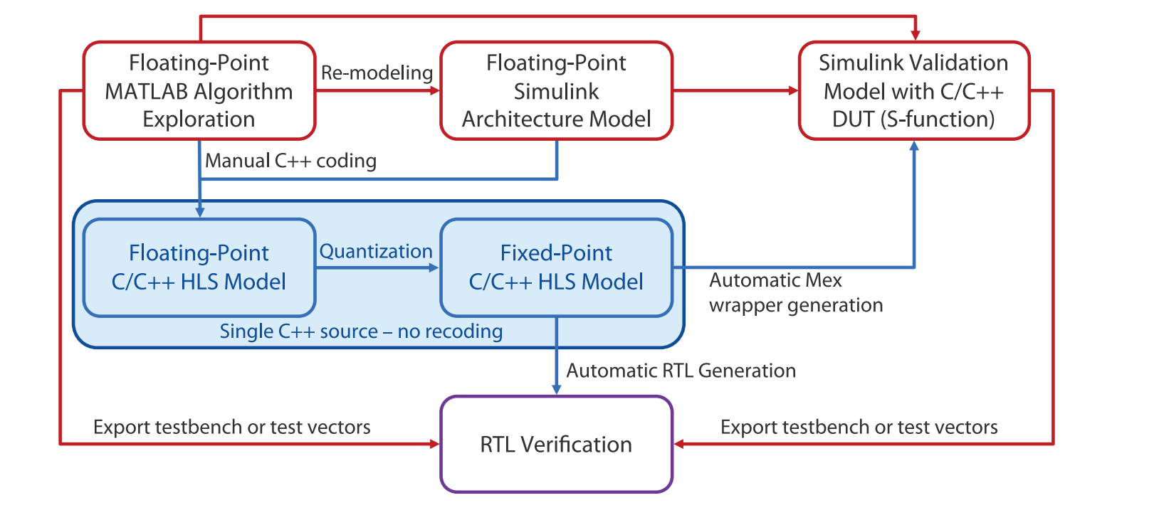
Mentor recently released a white paper on how architects and designers can streamline this flow for fewer surprises and less effort. This starts in the same place with the MATLAB algorithm and Simulink architectural model. It first removes the Simulink hardware-level model step because, in the author’s view, it’s easier to translate direct from the architectural model directly to class-based C++ than to another more detailed schematic view. The second simplification results from being careful about data typing. If this is planned ahead, you can use the same C++ code for floating-point and fixed-point types, with the flip of a conditional compile switch. These changes together reduce need for 3 manually generated models down to two.
Making it work
The white paper goes into detail on how you should approach mapping data types between the two platforms. This part requires some thought in comparing Simulink data types with potential C++ implementation data types, to ensure you can easily switch between floating and fixed point typedefs. I’m guessing this is worth a little extra effort to make the rest of the flow much easier.
Now you can generate C++ code corresponding to the architectural Simulink model, with a class definition for each hierarchical block. Here the paper suggests that the Simulink model should use hierarchy effectively to ensure easy correspondence with C++ without unnecessary code duplication. Internals defining functionality of each class will of course be a redesign – you can’t use the Simulink library functions. Anyway this is where you will ultimately want experiment with implementations in synthesis – pipelining, memory architectures and so on. To get the real benefit of switching to a synthesis flow from an effectively schematic-based flow.
Validating C++ against Simulink
Building the C++ model from the Simulink architectural model is a manual step, so you need to validate correspondence through simulation. Catapult simplifies this by building an S-function from the C++. You can import this back into MATLAB and compare between this model and the architectural model. You can continue to use this push-button flow as you refine the implementation, regenerating the S-function as needed. You’d most likely want to do this as you experiment with quantization for example.
You can read the paper in full HERE.
Also Read:
A Fast Checking Methodology for Power/Ground Shorts
Mentor Offers Next Generation DFT with Streaming Scan Network
Mentor User2User Virtual Event 2020!
Share this post via:


Comments
There are no comments yet.
You must register or log in to view/post comments.