My new iPad lasts about 10 hours on a single charge and the A5X processor is designed with a 45nm process from Samsung. Processor chips for tablets like this use a multi-voltage IC design flow to reduce total power by:
- Using different voltages for different blocks (the lower the voltage the lower power)
- Using dynamic voltages for some blocks to get better performance or lower power
A recent White Paper from Mentor Graphics explained how their IC implementation system called Olympus-SoC is used in a multi-voltage IC design flow. Note that my example of the iPad does not imply that Apple used Olympus-SoC.
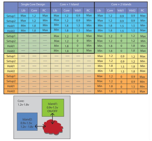
Using a multi-voltage IC design approach causes an increase in analysis steps, creating the acronym MCMM (Multi-Corner Multi-Mode). Consider a hypothetical IC design where:
- The core operates at 1.2V or 1.8V
- One power island runs at 0.9V to 1.2V and can switch on and off
- A second power island operates at 0.9V to 1.5V
With these multi-voltage design parameters the following table shows the number of corners and power states required for analysis:

Mentor’s approach will simultaneously analyze all combinations of library models, voltages and interconnect corners for all modes, corners and power domains. For low-power designs this approach will:
- Automate the multi-voltage flow, supporting Dynamic Voltage and Frequency Scaling (DVFS)
- Supports Clock Tree Synthesis (CTS)
- Optimize for both power and timing
- Make use of the Unified Power Format (UPF)
Steps in the design flow are:
- Import your design by reading files like: LEF, lib, SDC, Verilog and DEF.
- Setup the power domains using UPF, create physical domains, add power structures, identify IO rows, etc.
- Setup for timing verification.
- Constrain the placement
- Verify the power domains through a series of automatic checks: level shifters, isolation cells, always-on connections, etc.
- Setup multi-voltage checks before Clock Tree Synthesis to avoid port punching on domain interfaces, and define how to route around domain boundaries.
- Perform Clock Tree Synthesis and clock routing, create the clock tree and size the buffers automatically.
- Use gas stations (regions of constant supply) for top-level buffering, and allow routing over the top of a voltage domain.
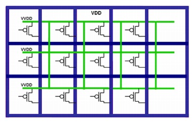
- Use Multi-Threshold CMOS (MTCMOS) switches to reduce leakage current.
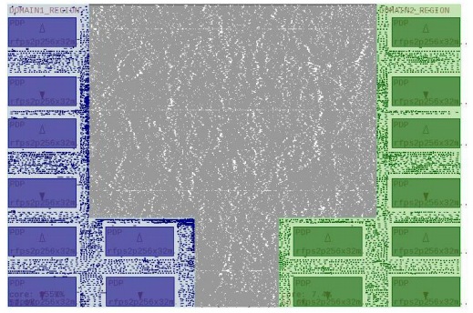
- Use a GUI to make analysis easier with colorful visualization.

Power domains have been placed by color, placement restrictions can be verified

The constant supply is labeled VDD and shown in purple, the variable supply is labeled VVDD and is shown in green and can be switched on or off.
Summary
Consumer electronics is the main driver in semiconductor design today, so optimizing for power is a requirement. The Olympus-SoC tools from Mentor Graphics enable power closure using:
- MCMM optimization
- Support for multi-voltage design
- Low-power CTS
Read the entire 11 page White Paper here.
Share this post via:


Comments
There are no comments yet.
You must register or log in to view/post comments.