webinar IPXACT banner

Sony Endorse FD-SOI to Attack Wearable & IoT

Sony Endorse FD-SOI to Attack Wearable & IoT
by Eric Esteve on 02-10-2015 at 12:04 pm

We are writing about FD-SOI technology since the beginning of 2013 in Semiwiki. So far, most of the design experience was related to ST-Microelectronics (even if IBM and GlobalFoundries have been actively working on the technology, probably more on a research mode than pure production). Sony being actively working to develop consumer products on FD-SOI technology (since 2012) is a real indicator about FD-SOI momentum in the SC industry. The paper presented at the SOI forum in Tokyo last month is here.

Sony is playing in the consumer electronic (CE) segment, probably the most crowded after the mobile. An OEM can play different strategies to win in the CE segment, for example developing “me-too” products, cheapest than the original, but with no differentiators. That’s not the way Sony is playing! Sony is an OEM (developing IC internally when it make sense) being recognized as one of the most innovative in the industry, and Sony’s winning strategy is to launch highly differentiated new products. When talking about wearable and IoT, ultra-low power is certainly one of the most important differentiator. If you analyze this well-known formula:

Power = af C V[SUP]2[/SUP][SUB]dd[/SUB] + I[SUB]leak[/SUB] V[SUB]dd[/SUB]

You understand why Sony has heavily invested into FD-SOI to develop IC targeting wearable and IoT. Designing with FD-SOI allow minimizing the two components of power consumption:

  • Running the device at a much lower Vdd (0.6V instead of 1.1V) than Bulk CMOS dramatically divides the active power consumption (in V[SUP]2[/SUP][SUB]dd)[/SUB]
  • Because FD-SOI active device is by nature built on Insulator, the leakage current is lower, so the related power consumption (I[SUB]leak[/SUB] V[SUB]dd)[/SUB]

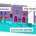
I realize that we have mostly write about high complexity (and high performance) logic IC designed in FD-SOI, like Application Processor or IC supporting communication infrastructure. But SOI in general and FD-SOI can be extremely effective for RF design as well: on the above picture Low power RF device exhibits:

  • Very high Intrinsic Gain for FD-SOI 28nm, compared to Bulk 28 or 40nm
  • Comparable noise

Sony has developed an analog chip in 28nm FD-SOI to explore the possibility to design an extremely low power GPS, opening the door for wearable GPS devices. It’s very exciting to see that FD-SOI analog behavior is very promising, like the pure logic behavior. If you look at Sony presentation here you realize that the assessment process has been extremely stringent: the design team has optimized the libraries, designing various gate length options, verified the minimum Vdd to run SRAM, on top of the analog specific simulation and measurement above described. Designing IC for GPS localization, as I have learned a couple of years ago when consulting for an ASIC customer, requires the availability of: High performance analog front end, relatively large on-chip SRAM, very sophisticated algorithm (the real Intellectual Property in fact)… and obviously the right embedded CPU to run these algorithms.

Sony has demonstrated in this presentation that FD-SOI was a very good choice to support such GPS application (thanks to the availability of high performance ARM CPU core, already demonstrated by ST-Microelectronics on the technology), offering even better analog performances than an equivalent Bulk node. But the true killer is the ultra-low power consumption demonstrated on FD-SOI, allowing developing consumer application, wearable or IoT, with a strong competitive advantage. If the effective power budget is 1/10[SUP]th[/SUP] of the equivalent on Bulk, this means that the “thing” you are wearing will need to be charged a couple of time a month instead of every day. This can make the difference for the end user: are you ready to buy another system that you have to charge every day, on top of your smartphone, your smart-watch, etc…?

Sony sharing about their design experiences with FD-SOI is almost a symbol: FD-SOI penetration in consumer application has started!

Next “rendez vous”: SOI Forum in San Francisco on February 27[SUP]th[/SUP], to register: RF-SOI and FD-SOI Forum San Francisco

From Eric Esteve from IPNEST


Chips Are Going 3D, DRC Needs to Go 3D Too

Chips Are Going 3D, DRC Needs to Go 3D Too
by Paul McLellan on 02-10-2015 at 7:00 am

The last paradigm shift in DRC was around 0.35um when designs got too large to handle as flat data, and hierarchical approaches were required. Back then the design rules themselves were not that complex, the explosion of data volume came from the complexity of the design itself. But each process node added more design rules intricacies and many new types of rules that needed to be checked.


Until recently, design rule complexity has been increasing around 20% per node (plus the designs continue to get bigger, of course). Now, advanced technology node complexity has exploded either due to FinFETs (for SoCs) or 3D NAND flash and much deeper trenches for DRAM (for memories). The world has gone 3-dimensional, and it’s getting very difficult to use inherently 2D checking methodologies to find 3D design problems. Often a single 3D “problem”, when abstracted to 2D DRC syntax, can drive thousands of individual design rules and entire chapters in a design manual. Since design rules have to account for small but inevitable variations in the manufacturing process, the development of these rules needs to understand the complex relationship of structure to process and design in 3D. For example, it is extremely difficult by examining the mask designs to verify that the fin height of the FinFET produced by those masks is within tolerance…or that this fin height variation won’t cause gate shorts to nearby devices. In effect, there has to be a very indirect and inefficient model of the manufacturing process hidden away in the rules and the DRC algorithms.

Coventor has a product, SEMulator3D that is inherently three dimensional. SEMulator3D is a virtual fabrication platform that many foundries and memory companies use to speed advanced semiconductor processes to market. Relying exclusively on test wafer manufacturing is too expensive and too slow for the continued fast pace and competition for advanced semiconductor products. When SEMulator3D is used for process development it reads in layout and a description of the process recipe and produces a full predictive model of what is going to end up on the wafer. The underlying technology uses voxels (the volume equivalent of a pixel). This is just the foundation required to make a much more direct, accurate and efficient interrogation of the 3D structures on the chip.

Virtual fabrication can be used to augment the conventional DRC approach, which is well suited for some things, with a 3D approach that creates an accurate and predictive view of what those masks create on the wafer. New capabilities in SEMulator3D allow three dimensional rules to be applied to virtually fabricated models. For example, technology developers can build up a complete 3D FinFET based on the masks and then measure critical aspects such as the fin height, spacer thickness and gate isolation much more directly.

Coventor has been actively developing the SEMulator3D technology to apply these 3D design rules to advanced technologies and product designs. It has just been granted a patent in this area and is now expanding its relationship with customers and partners to advance this 3D checking technology to augment the current DRC programs. Of course, it will take time for this 3D checking technology to mature and be ready for production-level sign-off. However, it is already showing great promise. This promises to be the next paradigm shift in DRC technology and should considerably improve the creation and application of design rules in advanced 3D technologies.


Open Forum for Semiconductor Professionals!

Open Forum for Semiconductor Professionals!
by Daniel Nenni on 02-09-2015 at 8:00 pm

The semiconductor industry has never been more exciting than it is today, at least not in my 30 years of experience. Things are moving faster than ever before making collaboration at all levels a requirement. At SemiWiki we are afforded the privilege of passes to semiconductor conferences around the world. We also have access to all levels of the fabless semiconductor ecosystem and speak with people both on the record and off. Even so, some of the best information comes from forum discussions, absolutely.

When we first started SemiWiki it was really meant to be a forum with wikis and a place for my weekly Silicon Valley Blog. Fortunately industry experts Paul McLellan and Daniel Payne agreed to move their blogs from EDN to SemiWiki and the rest is history. We now have eight industry experts on staff and dozens of others who blog when they have something of semiconductor interest to say.

The forums however are a different form of communication and a very important one. As you can see we have expanded our forum section to include additional subject areas:

Semiconductor Process Technology
TSMC, Intel, Samsung, GF, UMC, SMIC, 28nm, 20nm, 16nm, 20nm, 10nm, etc…

Electronic Design Automation (EDA) Software
Cadence, Synopsys, Mentor, Ansys, Atrenta SpyGlass,, Calypto, Carbon Design, ClioSoft, Coventor, Dassault, Fractal Technologies, Methodics, MunEDA, Silvaco, Tanner EDA, Etc…

Discussions on the latest SoCs and related technologies
CPU, GPU, LTE, 4G, etc…

Semiconductor IP Market Place Threads
A place to share your IP! DSP, PCIe, USB, DDR, MIPI, HDMI, NoC, etc…

Programmable Devices
Discussions on FPGA, PLD, and CPLD technology, design, and implementation, Xilinx , Altera, Lattice, and Cypress.

Microcontrollers
Discussions on embedded technology, design, and implementation
ARM, Analog Devices, Atmel, Freescale, Infineon, Intel, Maxim, Microchip, NXP, Renesas, Silicon Labs, STMicro, TI, Zilog

Mobile Devices
Discussions and product reviews for smartphones and wearables. Post a review of your favorite mobile gadget and lets crowdsource!

Internet of Things (IoT)
Discussions on IoT and Security. SemiWiki is staffed with IoT experts so this is the place to ask questions, absolutely!

Digital Fabrication: 3D Printing, CNC Milling, Laser cutting, etc…
Discussions and meet-ups on the latest technologies for digital prototyping.

Semiconductor Related Stocks
Where investors and semiconductor professionals interact. Please put stock ticker in subject of all posts: INTC, TSM, QCOM, ARMH, ALTR, XLNX, SNPS, CDNS, MNTR, Etc…

Semiconductor Related Jobs Forum
This is an open forum for recruiters and job seekers. Post jobs here for free! For the greater good of the semiconductor industry!

Each forum will have moderators so if you see one you are passionate about and would like to be actively involved let me know. There is fame but no fortune unless you consider the knowledge and relationships you will gain which is truly priceless. You will have direct connections to hundreds if not thousands of semiconductor professionals in your area of interest. Just imagine the possibilities!

As I mentioned in my blog “EDA Tool Reviews” we want honest and unfiltered opinions, observations, and experiences with tools and technology for the greater good of the fabless semiconductor ecosystem. The same goes for the other forums. Start discussions, ask questions, share your semiconductor design successes and failures so we all can all learn from them. Be an active part of the crowd that changed the world because our work is not done.

It is easy to get started, just register for SemiWiki (use your real name or not) and pick the forums that interest you. While you are in the forum just click on the Forum Tools tab and subscribe so you get notified whenever there is a new post. Or you can subscribe to the RSS feed, simple as that.


Writing the unwritten rules with ALINT-PRO-CDC

Writing the unwritten rules with ALINT-PRO-CDC
by Don Dingee on 02-09-2015 at 11:30 am

EDA verification tools generally do a great job of analyzing the written rules in digital design. Clock domain crossings (CDCs) are more like those unwritten rules in baseball; whether or not you have a problem remains indefinite until later, when retaliation can come swiftly out of nowhere.

Rarely as overt or dramatic as a bench-clearing brawl, metastability and other issues due to CDCs can be very hard to spot. Static timing analysis is of little help. Functional simulation may or may not have executed enough timing scenarios. At-speed testing in real silicon is an expensive and late way to discover a problem. Is there an alternative, pre-silicon?

The new release of Aldec ALINT-PRO-CDC 2015.01 provides designers a way to capture experience in debugging CDC issues before they start. Linting, or design rule checking, sifts through HDL code looking for constructs that match or violate a set of rules. This provides a way to automate code review, highlighting areas that may lead to problems.


What rules to use to stop CDC problems that are difficult to discover seems to be a problem in itself. This is where experience and the previously unwritten rules come in. ALINT-PRO-CDC accepts a set of design constraints. A key feature added is the ability to read Synopsys Design Constraints (SDC) 2.0 files. This brings in information used to aid synthesis, such as:

  • create_clock, create_generated_clock – specifies clock network sources and relations between them
  • set_clock_groups – defines groups of clocks that are asynchronous to each other
  • set_input_delay, set_output_delay – relation of the input signals to design clocks
  • Set of commands used to access design elements – get_clocks, get_pins, get_nets

Without knowing what the constraints were prior to synthesis, this information can be difficult to glean from HDL code alone. Most EDA platforms deal with SDC 2.0 files.

Aldec has gone a step further, allowing teams to add constraint extensions. This can help describe elements such as custom synchronizers, encrypted IP, behavioral models, FPGA vendor primitives, descriptions of reset networks, and other constructs. If particular areas of a design, or certain approaches, have led to CDC issues in prior debug activity, that information can be captured in the form of constraints.

Once constraints are established, ALINT-PRO-CDC goes in with advanced technology. Its synthesis engine looks at clocked elements and performs conditional analysis. A pattern matching engine validates synchronizer structure and finds forbidden netlist patterns. Clocks and resets are detected automatically, and clock domains are extracted.


The strategy reaches beyond only static checks – ALINT-PRO-CDC features integration with Aldec Riviera-PRO for dynamic checks at simulation. This greatly enhances capability for metastability insertion, precisely targeting areas in designs rather than randomly hunting around. Additional assertions and coverage statements help make sure CDC issues are exposed.

Linting is a fabulous tool – perhaps most famously applied in the Toyota sudden acceleration investigations – to find and highlight subtle problems in code that may lead to defects. HDL design is philosophically no different than software design, and it is surprising linting is not being used more broadly in EDA circles.

Aldec is hoping to not only help designers prevent CDC-related bugs, but to add another tool to the safety-critical design formal verification process such as called for in DO-254. With the increase in third-party IP and growing design complexity, the burden on designers to review code without automation help is becoming dangerously high.

Writing the unwritten CDC rules can prevent problems later in the design season. For more information, including an overview presentation, see the Aldec ALINT-PRO-CDC home page.

Related articles:


A Public Synchronizer

A Public Synchronizer
by Jerry Cox on 02-09-2015 at 7:00 am

You might ask yourself “Why would anyone want to have a public synchronizer available to download?” Usually designers just grab a flip-flop from his or her company’s or a standard cell vendor’s library. However, are these handy solutions the best course of action today? Current SoC designs have numerous clock domains providing many opportunities for metastability mischief at the crossings between these domains. Using handy solutions without fully understanding their reliability is dangerous for the design of safety-critical products

Modern flip-flop designs use high Vth transistors to reduce power while maintaining low clock-to-Q delay, but ignore synchronizer performance. Some firms have developed specialized synchronizer standard cells with high mean-time-between failures (MTBF). This measure of reliability depends on the synchronizer’s recovery time-constant tau and vulnerability window Tw. In safety-critical designs, synchronizer MTBF can be improved substantially by reducing tau at the expense of power and clock-to-Q delay. Such specialized designs provide a competitive advantage and are usually considered confidential IP that must be kept hidden.

Keeping the design and performance of these private synchronizers under wraps makes it impossible to compare their performance or establish benchmarks. Engineering students and researchers’ understanding of synchronizer subtleties is hindered.

To overcome these drawbacks our colleagues at Oracle and Southern Illinois University Edwardsville have developed a public synchronizer that provides many benefits:

  • Engineers can use the public synchronizer’s extracted netlist to compare a synchronizer MTBF obtained with their in-house analysis tool against that obtained with MetaACE, a Blendics tool verified in silicon.
  • Designers can layout the public synchronizer in their current process so that it serves as a benchmark for new designs.
  • Researchers and engineers can use the public synchronizer to investigate the effect of changes in semiconductor processes (P), supply voltages (V), or junction temperatures (T) on MTBF and do this without exposing details of their private synchronizer design.
  • Students can use the public synchronizer‘s extracted netlist and the associated FreePDK to study synchronizer design issues.

The above benefits sound useful so let’s look at the Public Synchronizer design. Two cascaded level-sensitive multiplexer-based latches, a master and a slave, were chosen as the basic design and for good testability a Level Sensitive Scan Design (LSSD) was also included. Although a synchronizer and a data flip-flop use this same circuit, the characteristics to be optimized are very different. Ian W. Jones of Oracle Labs, suggested a design based on a standard textbook circuit. George Engel and Sam Dunham, both at Southern Illinois University Edwardsville, optimized transistor sizing for synchronizer service and completed the layout.

This layout and fully extracted netlist were obtained using the FreePDK, a purposely non-manufacturable, Free Open-Access 45nm Process Design Kit and Standard Cell Library from North Carolina State University. The public synchronizer circuit occupies an area of 16 sq μm and possesses a t(CLK−Q) of 55ps. An analysis by the Blendics tool, MetaACE, gave a tau(eff) of 13ps and a Tw of 43fs when the synchronizer was operated from a 1.0 Volt supply. For clock and data rates of 1.5 GHz and a 50% duty cycle, the synchronizer MTBF is 1.6 x 10e6 years assuming 85% of a full clock period is available for synchronizer resolution. A two-stage synchronizer with the same clock rate, data rate and resolution-time assumption would have an MTBF of 5.5 x 10e37 years, a much more prudent value for a safety-critical application with a production volume of a million or more units.

Try the public synchronizer using your process. How does its MTBF compare to what you have been using? If you don’t have a convenient way to measure MTBF download MetaACE LTDand attend the Blendics webinar.


Webinar: How IoT Designs Driven by Cost Power Security

Webinar: How IoT Designs Driven by Cost Power Security
by admin on 02-08-2015 at 8:30 pm

SoCs being developed for the fast growth Internet-of-Things market will sell for and operate on a small fraction of the power of mobile devices’ chips. More importantly, IoT SoCs will be far more vulnerable to hacker attacks than the much better protected chips in portable devices. As a result, designers developing SoCs targeting IoT applications face a set of challenges that require computing capability unique to this class of devices: (1) extensive power management functionality, (2) sensor data and network protocol stack processing, (3) detecting and thwarting security attacks, (4) and enabling all these functions in a silicon footprint no larger than an 8-bit alternative.

Andes Technology Corporation will host a webinar on Tuesday, February 10, 2015 at 10:00 AM Pacific Time, that will detail how IoT designs are driven by cost, power, and security. One IoT device example that will be described, the smart meter, serves to illustrate the importance of these design considerations. It contains an analog interface from a sensor providing voltage, current, and temperature readings. A microcontroller in the design performs the compute functions for the design. In addition, there is a communications port, power-line communications, Zigbee, or some form of RF interface. For program and debug the design typically comes with an interface to external PC.

The 8-bit processors first used in IoT applications have a simple CPU architecture and instruction set, developed in the early 1970s, suited to control applications 30 to 40 years ago. With the rise of the smart phone, the computing requirements changed dramatically and demanded a 32-bit architecture, that were designed in the late 1980s, able to run on rechargeable batteries. Both these processors are being applied to the new Internet-of-Things devices now coming on the market, but neither provides the adequate computing architecture and instruction set required by this next generation of products.

The 32-bit embedded processor of which there are a number of alternatives provides the compute power, but suffer the problem of being designed for applications that were the major market drivers of their day: the PC, set-top box, and the mobile phone, tablet, and variety of consumer devices—cameras, audio recorders, and so on. The functionality in these 32-bit processors has yet to deliver a hit end-IoT product, comparable to the smart phone. For example, activity trackers and smart watches fall short on power and end user capability.

What the Internet-of-Things requires is a 32-bit processor with an architecture that serves the demand for high performance, while providing the power savings needed to last long periods between recharge or to run on harvested power. This webinar presents one such 32-bit embedded processor system. Designed in 2005 from the ground up, the Andes Technology N8 MCU plus AE210 peripherals will be used to illustrate how new architectural features can achieve both performance and power savings in a gate count comparable to an 8-bit CPU. Two features that will be described to drive home the point are frequency scaling and flash acceleration, neither supported directly on existing 32-bit embedded CPUs.

To provide the demand for enhanced security, the presentation will also describe hardware functionality built into the new 32-bit architecture: data and address scrambling and differential power analysis protection. The first provides protection from hacks that target the interface between CPU and memory. The second protects from hacking the program by observing the power use signature of the CPU.

Please join the webinar on Tuesday, February 10, 2015 10:00 AM – 11:00 AM PST. To register, click here.

By Emerson Hsiao, Senior VP, Sales and Technical Service, North America Operations


Integrated Spec Design & Documentation for SoC

Integrated Spec Design & Documentation for SoC
by Daniel Payne on 02-08-2015 at 1:00 pm

One challenge in SoC projects is maintaining consistency between the specification, design and documentation throughout the product lifecycle. Imagine the chaos if your specification for power is 300 mW, the design is actually 350 mW and the documentation promises 250 mW. Traditionally the design and documentation process are separate and unrelated, creating opportunities for discontinuities. One company that has decided to focus on keeping specification, design and documentation consistent is Magillem, and they delivered a capability called ISDD (Integrated Specification, Design & Documentation) back in May 2014.

In this methodology you would use a Magillem front-end capture tool using common parts (instances, configurability, interfaces, hierarchy, partitions, hardware-software interfaces) that then automatically generates all of the representations from a single source. There is an Accelleara standard called IP-XACT/IEEE1685 that uses the XML schema to define IP blocks. What the Magillem approach does is to use the XML schema to link the specification of design elements captured in IP-XACT with a set of XML fragments for documentation content. As your design changes you can propagate updates to the associated documentation. Using standards like XML you can now aggregate design data with any external product information.

Related – TLM Modeling Environment and Methodology Goes Commercial

So your entire SoC becomes a coherent set of hardware descriptions, software and documentation, all tied together through XML. Product Lifecycle Management (PLM) tools from companies like Dassault Systemes connect with the Magillem Content Platform providing you with:

  • IP catalog
  • Defect management
  • Revision control
  • Configuration control

Customers like ST Microelectronics are using this ISDD approach from Magillem in their SoC development process.

Magillem has a lot of experience with XML-based tools, and with their Content Assembly Platform have served diverse markets like legal and technology. They are also members of: Accellera, Cadence Connections, OCP IP, ARM connected Community, EDAC and ARTEMISIA.

Related – A Brief History of Magillem

Summary

It is now possible to maintain consistency between all of the representations in an SoC by using a single source that keeps everything updated. Hardware, firmware and documentation can all be connected, instead of separated and disjointed.


FD-SOI at Samsung

FD-SOI at Samsung
by Paul McLellan on 02-08-2015 at 7:00 am

Various foundries have made announcements about licensing FD-SOI technology from ST Microelectronics and then fallen quiet. GlobalFoundries made an announcement a couple of years ago. Samsung made an announcement just before DAC last year. But neither company has said anything much since. Of course the big noise at 14/16nm is all around FinFET but the reality is that the number of designs moving to those process nodes is relatively small. Many designs are remaining at 28nm or larger processes (TSMC has re-architected their 45nm and 65nm processes to have ultra-low power versions for example). FD-SOI is seen as a good way to extend 28nm by giving it most of the characteristics of 20nm, even lower power if the biasing is used, at a slightly reduced cost since it is slightly cheaper to manufacture than bulk planar. In particular, I don’t see IoT designs being 14/16nm SoCs and older processes where the analog and RF are easier are probably going to be the workhorses for those markets (I hesitate to call IoT a market but it is certain that lots of devices will be connected to the internet in the coming years).

As if to emphasize this, Yongjoo Jeon titled his presentation 28FD-SOI Cost Effective Low Power For Long-lived 28nm.

Yongoo started with a history of technology migration. Down to 130nm we scaled everything including the gate-oxide thickness but that ran out of steam then. Since then we have had copper interconnect at 90nm, low-K dielectric at 65nm, stress engineering at 45nm and Hi-K metal gate (HKMG) at 32/28nm. Basically the era of material innovation. At 20nm planer hit the gate length scaling limit and the two structure innovations going forward are FinFET (at 22nm if you are Intel and 16/14nm if you are not) and FD-SOI (initially as a retro-fit to 28nm processes).

One of the challenges faced by FD-SOI has been the perception that it is only available and used by ST. Customers want alternative sources. Of course they need other stuff too, such as low cost per transistor, IP support, performance and, above all, low power. With Samsung, the worlds #2 (or #3 depending on how you count) foundry the process has a lot more credibility.

Last month in Tokyo was the FD-SOI and RF-SOI Forum in Tokyo Samsung presented on FD-SOI. Another interesting looking presentation is by Sony who are using 28nm FD-SOI for RF design, but their presentation is not yet available so I don’t have details, but the fact that customers (as opposed to foundries) are starting to endorse the process is more good news for the ecosystem.


Samsung emphasized the cost aspects since there are 289nm FD-SOI has fewer process steps than bulk 28HKMG and the BEOL (metal) is the same. The simpler process helps to offset the fact that the SOI substrate is more expensive than bulk.

Compared to 28HKMG the performance is better, the power is lower and the area is the same. And it is much better in all dimensions than either 45bulk or 28PSION.


Samsung emphasized that the better short-channel control means a shorter channel length and more gate bias. This gives two knobs to control performance and leakage. Gate CD-biasing, which is physical, and body-biasing which is electrical and can be used to reduce leakage when performance is not required or the circuit is idling. But where FD-SOI really shines is that the voltage can be further reduced down to 0.63V with reasonable performance and much lower power.


Samsung did a full qualification of the process completed in September 2014 and both the pmos and nmos transistors passed everything.

The business model on the IP side is that IP vendors will supply everything except the foundation libraries which will be delivered by Samsung themselves. I don’t know if any of this work is shared with ST or if Samsung have a completely separate ecosystem.


Has the Semiconductor Industry Gone Mad?

Has the Semiconductor Industry Gone Mad?
by Daniel Nenni on 02-07-2015 at 7:00 pm

The weather in Taiwan last week was very strange. It was so cold I tried to turn on the heat in my hotel room only to find out it was not possible. If you want more heat they bring a portable heater because who needs central heat in Hsinchu? Even stranger is all of the media hyperbole on the next process nodes:

Intel CFO: We’re so far ahead that Apple has no choice but to work with us

What he actually said is that Intel is so far ahead of the competition when it comes to PC processors that Apple (and just about every other PC maker) has no choice but to use Intel chips. True as that may be I’m not sure reminding everyone that you have a monopoly on the PC business is such a great idea. In regards to Apple it is hard to tell what they will do for semiconductors. At one time the media thought that Apple would no longer do business with their competitor (Samsung) after successfully moving to TSMC at 20nm. Now the media has “affirmed” that Apple is using Samsung 14nm exclusively for the iPhone and iPad this year:

Apple affirmed to return to Samsung for 14nm ‘A9’ chips for next iPhones, iPads

As I have said before, no one likes a monopoly so I find it highly unlikely that Apple will use just one foundry if at all possible moving forward. Given that they make two different chips, one for the iPhone and a larger more powerful one for the iPad, it makes using two foundries that much easier. You should also know that Samsung 14nm is LP (low power) while TSMC 16nm FF+ has a higher performance range so making the A9 at Samsung and the A9x at TSMC is much more believable.

The other thing you should ask yourself is why did Samsung and GlobalFoundries REALLY do the 14nm licensing deal last year? The answer is because customers “suggested” they do so. And by customers I mean the two largest wafer customers which are Apple and Qualcomm of course. I remember Paul McLellan and I being briefed on this last Spring and me thinking to myself, “Has the semiconductor industry gone completely mad?”

Samsung ♥ GLOBALFOUNDRIES

In a recent conference call TSMC called GlobalFoundries “Samsung’s accessory” which was funny but it also has a much deeper meaning. Given the choice of a single manufacturing source for a specific process node or a source with an “accessory” Apple or Qualcomm will chose the latter, which is what they have done at 14nm. There have been no announcements as to whether Samsung and GlobalFoundries will again work together (copy exact) on 10nm but if Apple and QCOM say so they will, absolutely. You have to follow the money trail in the fabless semiconductor ecosystem for sure.

The other question I asked myself at the end of this trip was: “Self, how long until UMC becomes TSMC’s accessory?” And if this trend catches on who will be Intel’s foundry accessory?


Product Review: Bose – SoundTrue Around-Ear Headphones

Product Review: Bose – SoundTrue Around-Ear Headphones
by Daniel Payne on 02-07-2015 at 7:00 am

My old headphones with microphone lost a channel, so it was time to upgrade and I went shopping for something that had high fidelity and fit over my ears, instead of on my ears. After some online research I opted for the Bose headphones, because that brand has been around for decades, they offer many models to choose from, and are readily found at nearby stores like BestBuy. The model I bought are called SoundTrue Around-Ear headphones.

Pros
Comfortable enough for all-day sessions, while keeping sounds outside to a minimum. Faithful sound.

Cons
Using the microphone to speak with around-ear headphones sounds very funny because your own voice is muffled, so if you do a lot of talking with apps like Skype then buy an on-ear headset instead.

Summary
At $179.00 these headphones live up to the Bose reputation for faithfully producing sound, without over-emphasizing the bass like so many other brands do these days.

Commentary
At my local BestBuy store in Tualatin, Oregon I listened to several brands of headphones:

  • Bose QuietComfort Acoustic Noise Canceling Headphones
  • Beats by Dr. Dre
  • Skullcandy
  • Bose SoundTrue Around-Ear

There certainly are dozens of makes and models to choose from when it comes to headphones, so a lot of it for me came down to several factors:

  • Color – I prefer white
  • Fit, comfort
  • Brand reputation
  • Sound fidelity – for classical music and movies on Netflix
  • Build, quality
  • Price – under $200
  • Features – microphone

I was quite used to on-ear headsets, which sound great when making Skype calls because you can hear your voice in a natural fashion. The headphones by Dr. Dre and Skullcandy were OK, but they seemed aimed to the youth market where the bass is pumped up, while the Bose just felt, sounded an looked right to my aesthetic taste. My Acura RL also has a Bose sound system, so I was probably already a loyal Bose fan when looking for headphones.

When I first placed the headphones on in the store I was impressed by how much of the ambient store sounds were instantly cut off, letting me really concentrate on listening to the demo tracks playing. There’s a volume control built-in to the cord, so I could easily adjust by clicking up or down. The Bose brand with noise canceling was high-tech and attractive to me, but I didn’t really need that feature in my office use. Once I got home and listened to classical music with a symphony orchestra I was impressed, because I could hear each of the instrument sections clearly playing, there were no muddled frequencies or exaggerated tones.

I’ve enjoyed listening with these headphones connected to my MacBook Pro, iPad and Samsung Galaxy Note 2 devices. I can hear all of the conversations and directional sounds from movies, each instrument in classical music, all while keeping sounds in the room blocked out. It’s a real immersive experience for me.

Making a Skype or VOIP phone call was a surprise to me with this over-ear unit, as all of a sudden my voice was now being muffled by the headset itself, so I don’t recommend trying to use any microphone app with these.

Bose does provide a padded carrying case and a detachable cable with this product. I know that my son has literally worn out his gaming headset before, and it didn’t have a detachable cable and that was the first thing to break for him, although it wasn’t the Bose brand. The cable is 66″ long, which is just the right size when I watch Netflix on my laptop or listen to music.