webinar IPXACT banner

Why Would You Leave Yahoo to Go Into EDA?

Why Would You Leave Yahoo to Go Into EDA?
by Paul McLellan on 02-06-2015 at 7:00 am

I sat down this afternoon with Peter Theunis, the CTO of Methodics. Conveniently their office is about a 15 minute walk from where I live so we could chat face to face.

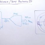
Peter started programming when he was 8 and his first “product” was a weather system for orchards where sensors in the orchards would send information back to a weather program that would advise the farmers when and what to spray the orchards with.

Peter came from Belgium as an exchange student at Berkeley, got a job at a job-fair and ended up staying in the US (I came for a couple of years, over 30 years ago, it happens to many of us). He worked for a couple of start-ups that didn’t start and then decided he had better join a larger company and get his green card. So he worked for a Telco in San Diego for a couple of years until they outsourced all their engineering to Shenzhen.

In 2006 he joined Yahoo and worked there for 8 years in a number of different jobs, including 2 years working for Marissa Mayer when she joined from Google to be come CEO. One thing that he found there is that nothing off the shelf works for Yahoo. Vendors would come by and they would ask “will it scale to 600M people” and the vendor would have to admit that it wouldn’t really. He also learned the importance of requirements and, for a company like Yahoo, latency, throughput, scalability and capacity.

He had known Simon, the CEO of MethodICs, for a while and even advised them on occasion. Simon caught him at the right moment when he asked him to give MethodICs a shot and come and be CTO. Since Peter (well, his wife) was pregnant, the attractiveness of walking to work rather than spending 3 hours a day on Yahoo’s buses from San Francisco was also a big plus. He joined Methodics in June last year.

The prospect of making more of a difference was also attractive. I asked him what he meant. “The purpose of every major site on the internet, such as Yahoo, is to get you to click on ads. That is the metric. How many ads got clicked on.” At MethodICs, while it is not curing cancer, it is enabling the semiconductor industry which in turn has made an enormous difference to the lives of almost everyone in the world over the last few decades.

When he arrived, he was surprised, shocked even, to really see that way that the design pipeline works. It is very inefficient with ad hoc processes involving thinks like email. It was obvious that MethodICs could add a huge amount of value by standardizing and automating processes, and moreover providing metrics that allow the processes to be improved over time.

He is overseeing the development of ProjectIC to make it even more secure and reliable, “enterprise grade”. It needs to be robust and easy to operate so that it can be installed, forgotten about and will run for a decade (as opposed to internet software where 2 years is the maximum life before upgrading it completely). Simon asked him to “think outside the box and bring some of the Yahoo approach to the table.”

One big area is testing. Yahoo has hundreds of packages to be deployed to, perhaps, a thousand hosts. Simultaneously. There is a need to test combinations, multiple versions, automate the testing. IP has a lot of the same issues with multiple versions, complex interactions and lots of views. Software testing has changed from throwing it over the wall to Q/A to where testing (unit testing) is part of the development methodology with analytics to improve the flow.

Since semiconductor companies have often grown through acquisition, they often have multiple flows and, often, installation procedures that are not automated but are manual. It is not possible to change these flows or processes, especially in the middle of a project, so MethodICs needs to be flexible, to automate what can be automated but also support manual processes.

Peter has lots of ideas for the future as MethodICs brings on board a number of world-class computer scientists. We will all be watching.


Cadence 2014 Results

Cadence 2014 Results
by Paul McLellan on 02-05-2015 at 7:01 pm

Cadence announced their Q4 and 2014 results yesterday. They are the only one of the big 3 EDA companies whose fiscal year is the calendar year so Synopsys and Mentor will not be joining them in announcing them this week.

I won’t go into the numbers in detail, you can find them all easily enough. But it is a pity that statements like this can’t be backed up with the company names:We had over 10 full flow digital wins in 2014. We also had segment share gains at several leading customers, including a global marquee company and most recently at a major fables semiconductor company.

Lip-Bu said that Tempus/Voltus/Quantus had more than 50 tapeouts which is impressive considering how new these products are. Of course it is possible for Synopsys to claim the same tapeouts, perhaps. I’ll bet risk-averse design groups (that would be all of them) run PrimeTime as well as Tempus, for example.

Palladium emulation seems to be doing well. This is a particularly sensitive area since margins on a product like Palladium are lower than a pure software product and the market has recently become very competitive. For once we have a name, and a good one, in that MediaTek doubled their Palladium capacity last quarter. Cadence have their next generation emulation (presumably still called Palladium) which is shipping in the second half of this year. In the questions it was admitted that the product was late (“took a bit longer”) but that it will have higher margins than the current product line.

IP grew 40% in 2014 vs 2013, led by DDR (the outgrowth of the Denali acquisition) including by HiSilicon earlier in the year with the world’s first 16FF tapeout. Tensilica had the largest number of new licenses ever last quarter and also passed the 2B cores/year run-rate in production. Then in the questions it is clear Cadence is having some major success at 10nm in IP too:In the most advanced 10-nanometer we won and in fact the largest IP contract to-date and with one of our largest top customer.

You might remember that the Virtuoso product line got split into the original version for mature nodes and Virtuoso for advanced nodes used for 20nm and below (with support for double patterning, FinFET etc). Over 40 customers are using the advanced node version.

For a number of reasons, Palladium just being one of them, margins were guided down in the first half of next year. Other factors called out in the questions: social security payments run in the first half of the year until they meet the cap; vacation is mostly taken in the second half of the year. They also said that margins are under pressure from their investment in technology and in customer support for their major new customer wins. They are forecasting a 6% top line growth for 2015, slightly faster than the overall EDA industry and faster than the world economy.

Lip-Bu was asked about the extra investment and margins and would margins expand in the future as the investment started to earn a return. Lip-Bu gave one of his inscrutable answers which is not clear whether the answer is yes or no:First of all, I think the investments are highly leveragable across customers. That will provide the leadership and market share as a key driver for success for our business going forward. And I am confident if we execute and then successful in the long-term and are proliferating our product more in the winning customer, marquee customer and also the next level of customer will be also embraced, that in the end, it will benefit in our shareholders.

Another interesting comment in the questions was about 10nm being a long lived node:clearly the 10-nanometer, the main reason as it is going to be a long node because 7 and 5 is unclear and EUV timing is unclear.

SeekingAlpha transcript of the call is here.


Google Glass: The Second Coming and a Brief History

Google Glass: The Second Coming and a Brief History
by Majeed Ahmad on 02-05-2015 at 4:00 pm

Google Glass is dead; long live Google Glass. That’s how Ori Inbar stated the recent closure of Google Glass beta-test project in his report titled “Smart Glasses Market 2015: Towards 1 Billion Shipments” released by www.augmentedreality.org.

Inbar says that Google, a smart glass pioneer, not only compromised its status in the promising wearable devices market by abruptly ending the program, but also hurt its Glass Certified Partners. He adds that despite privacy and cultural concerns, the project has raised public awareness about smart glasses to an unprecedented level.

Inbar contends that Google Glass is the best thing that happened to augmented reality since the iPhone. However, he acknowledges that it also drew harsh criticism from technophobes, ethics pundits, privacy defenders and fashionistas alike. And that trade press picked on that negative buzz and readily crafted catch phrases like ‘Glasshole’ and ‘Glass Half Empty’.

And now that Tony Faddell—the iPod pioneer and CEO of Nest—has taken the charge of Google Glass work, Inbar quotes reliable sources about the launch of the next version of the Google Glass later this year.

Google Glass History

In 2010, the Internet giant’s top-secret projects lab Google X began the development of this camera- and Internet-equipped wearable computer. The project was announced on Google+ by Babak Parviz, an electrical engineer who specialized on the interface between biology and technology and had worked on putting displays into contact lenses.


Parviz made the first Glass demo along with Sergey Brin
(Photo courtesy of Entrepreneur)

Steve Lee, a veteran product manager who specialized in location and mapping technologies, was also involved in the project’s initial development. Lee had earlier worked on Latitude, a Google app that enabled users to broadcast their GPS location to friends.


Lee was an early contributor to the Glass project
(Image credit: USA Today)

Thad Starner, a Georgia Tech professor who had been building and wearing head-mounted computers since the early 1990s, eventually became the technical lead for the Project Glass. Back in 2003, Starner had shown Google founders Larry Page and Sergey Brin a clunky version of a wearable computer that he had built at Georgia Tech.


Starner claims to have coined the term augmented reality

Glass was a pet project of Google’s co-founder Sergey Brin. The Internet-connected eyewear was released for developers in February 2013 and became available for consumers later in 2014. Google Glass was, in fact, a do-everything computer and information portal that boasted augmented reality technology and epitomized the next wave of disruption in mobile computing.

It represented a new class of wearable and embedded computers that first absorbed the smartphone capabilities and then promised to offer even more. Many industry watchers called Glass the next iPhone. It was a great idea that encouraged people to imagine and to create innovative new applications and spawn the brand new wearable industry.

The technology behind the Glass was game-changing. However, on the other hand, Glass was a product ahead of its time. It was a mini-computer on your face with a social twist; consumers at large were wary of it being a somewhat creepy device that secretly searched information for its owners.

Moreover, the product design of Glass didn’t go well in the fashion-conscious consumer electronics world where it was imperative for a personal device to look cool. The US$1,500 per pair price tag of Glass didn’t help either when it went on sale for just one day on April 15, 2014.

The second part of the article about Google Glass history is based on excerpts from the book The Next Web of 50 Billion Devices: Mobile Internet’s Past, Present and Future. The book is available in both paperback and e-book formats.


Concept: From Schematics to Debug

Concept: From Schematics to Debug
by Paul McLellan on 02-05-2015 at 7:00 am

In the late 1990s I was the VP Engineering at Ambit Design Systems. We had a synthesis product (called BuildGates, nobody ever forgot the name). Both our own engineers and our customers wanted to be able to take a look at the gate-level netlist that was generated from their RTL. We used a product from a company called Concept Engineering based in Freiburg, as opposed to Munich where almost all other German EDA is centered. This would take the netlist, place all the inputs on the left, all the outputs on the right and then run a placement algorithm (probably pretty similar to P&R placement) on the netlist to decide where to put the gates and then run a router (probably pretty different from P&R routing) to put all the wires in with the idea of making the final result as pretty and readable as possible. This worked really well on moderate sized designs but since BuildGates could take 1M gate designs and synthesize them flat, it didn’t work too well on that sort of design—but then there is no good way to display a million gate netlist well.We had an OEM agreement with them to ship this product, now called NLview, to our customers. So, as it turns out did everyone in EDA who needed a schematic viewer (except Synopsys who needed it a decade earlier). That business still exists and whenever in EDA you see an automatically generated schematic that is probably what you are looking at. They then extended the technology so it was possible to look at hierarchical designs, Verilog, SystemVerilog, VHDL. Then transistor level designs in SPICE. Basically take pretty much any input and display it in a way that was both pretty (didn’t look like a rat’s nest) and effective for an engineer trying to follow his or her way around the design.It turns out that this is perfect for the modern design style that is largely assembling IP blocks. One problem with most IP blocks is that they come from another part of the company or from a 3rd party. No matter what the format, the block can be displayed in a way that makes it easy for an engineer to move around the design, up and down the hierarchy and so on, to get an understanding of the block. Paths can be traced, drawn in different colors and so on. There is full cross-probing between the graphical display and the input and the levels of the hierarchy.But they went further and added a lot of debug features to create a product called StarVision Pro that makes debugging a design a lot easier than starting from just the opaque input file. Cones from inputs or specific pins can be traced, critical paths can be excised from a netlist and written out in SPICE for detailed simulation and a lot more capabilities that an engineer trying to understand and debug an IP block requires.There is a lot of capability for analyzing the clock, highlighting the clock trees and highlighting all the domain crossings from one clock to another.At the transistor level, where the netlist can be incredibly complex due to parasitics, there are features to prune the netlist, merge capacitance and resistance when they are small, automatic recognition of gates from transistor structures and even creating hierarchy out of flat netlists. Basically, they can read in a transistor-level netlist and make it a lot more intelligible to the designer without losing accuracy. Moderately large blocks can be read straight in fast, huge blocks can be pre-processed into a binary format in an overnight batch mode and then the binary loads almost instantaneously.


What’s Hot at SPIE Advanced Lithography

What’s Hot at SPIE Advanced Lithography
by Beth Martin on 02-04-2015 at 10:00 pm

The 40[SUP]th[/SUP] SPIE Advanced Lithography conference will be at the San Jose Convention Center 22-26 February. Over the past few years, this conference has grown in scope to include emerging patterning technologies, like directed self-assembly (DSA) and design-process-technology co-optimization.

Underlying all the presentations, posters, panels, and hallway chatter are common goals and challenges: keep the fabs working and yields high, while controlling cost and turn-around time as the law of physics work against you.

One key component of managing modern manufacturing is computational lithography, which includes:

  • Optical proximity correction (OPC) and resolution enhancement technology (RET) software and methodologies that achieve the maximum possible lithography entitlement
  • Software, applications, and methodologies that allow foundries to increase their productivity and thus reduce development cycle times and associated costs
  • Manage the post-tapeout flow

You will see plenty of this type of technology presented at the SPIE Lithography conference. There are papers on incorporating DSA in multipatterning, analyzing litho hotspots with pattern matching software, enhancing local printability in sub-14nm nodes, model-based mask preparation, new modeling of 3D effects, and managing OPC jobs for better productivity and use of resources. These technologies help maintain reasonable turnaround times for the entire post-tapeout flow and manage foundry production costs.

The importance of modeling
I talked to John Sturtevant, the director of modeling and verification solutions at Mentor Graphics about some of the hot topics in computational lithography. He said that there are significant modeling challenges associated with the 14 and 10 nm manufacturing process nodes, particularly the need for accurate and fast simulation of three-dimensional phenomena associated with the mask, wafer, and resist.

“3D EMF effects associated with mask topography have been effectively modeled for many years,” Sturtevant said, “and to support 14 nm, we added refinement of edge to edge crosstalk signals in DDM.” This enhancement leads to significantly better matching to rigorous simulation with very little runtime impact. Using the crosstalk DDM library results in better wafer fitness, especially when the mask absorber sidewall is optimized in conjunction with mask bias, he said.

Sturtevant points out that formerly “non-critical” implant layers now pose a significant OPC challenge. Underlayer topography models, which capture the complex array of wafer topography effects, have been deployed for 14 nm. These models are being expanded to better represent the impact of active FinFETs and the results for pre- and post-poly layer implant models have been excellent.

There is also new focus on the photoresist model. The 14 and 10 nm nodes feature extensive use of negative-tone develop (NTD) resist processes for the patterning of metal and via layers, due to the intrinsic aerial image advantage of a bright field mask. These NTD resist processes have unique shrinkage and develop rate properties compared to the traditional positive-tone processes. Sturtevant says Mentor has modified the CM1 model to support new NTD-specific modelforms, with a 40-55% improved accuracy in predicting wafer results. They have also rolled out improvements in the prediction of resist toploss and scumming as well as SRAF printing for both PTD and NTD cases.
DSA is now on the near horizon, and compact models predicting the assembly of vias inside of guiding patterns are already available to assist in development efforts. An important consideration for these models is to ensure the proper 3D formation of the vias. You can expect to hear a lot about DSA, and computational platforms for DSA, at SPIE Advanced Lithography this year.

So if you are involved in design for manufacturing or post-tapeout engineering, don’t miss SPIE this year from February 22-26, 2015 at the San Jose Convention Center.


Temperature Monitoring IP to Revamp SoCs

Temperature Monitoring IP to Revamp SoCs
by Pawan Fangaria on 02-04-2015 at 3:00 pm

With increasing density and functionality of chips at extremely thin silicon and metal layers, temperature has become critical. The temperature situation can become worse with wireless enabled 24/7 power-on devices. In such a scenario, a device must manage its thermal profile dynamically to keep the temperature within tolerable limits. Of course all precautions must be taken to budget for voltage, power and temperature while designing an SoC. It’s prudent to also have mechanisms embedded within the SoC so that it can self adjust its operations when temperature hotspots arise. What are such mechanisms? Thanks to the innovative IP world; it provides IP that can continuously monitor voltage and temperature, detect temperature hotspots and guide the chip to adjust temperature in the hotspot regions.

This Monday, it was a pleasant occasion to watch an on-line videoat Cadencewebsite where Bob Salem, Product Marketing Director at Cadence explained how such an IP works and can be used in chips to optimize their performance, increase reliability and lengthen battery life. This is actually an explanation on whiteboard, recorded and posted on the Cadence website on a Wednesday. Cadence popularly calls these videos as ‘Wednesday whiteboard videos’! Let’s see what is there to learn in it.

Looking at the thermal imaging of a die, maximum temperature can be seen at a hotspot. The temperature degrades as we move farther from the hotspot in all directions. In the above picture, a hotspot is shown at 125[SUP]o[/SUP]C and the outermost circle periphery is at 40[SUP]o[/SUP]C. The first problem at hand is to locate the hotspots on the die and then take appropriate steps to cool down those areas.

On the left side in the above picture is a simple conceptual circuit diagram of the circuitry that goes into the voltage / temperature monitoring IP. A multiplexor takes multiple inputs from sensors for temperature, voltage, and percentage of moisture in a particular area where the IP is located and outputs the desired information in analog form. The analog data is then converted into digital form by an ADC (analog to digital converter). The digital data goes into a processor which deciphers the information and takes appropriate action. Depending upon the severity of temperature, either it can turn-off the power or lower the frequency of operation in that region.

As shown in the thermal profile diagram, the IP blocks can be spread across the die to record and process the voltages and temperatures in different regions. A good IP and well designed topology of an SoC and IP placement regions within it can be very effective for the SoC to manage its temperature profile to be within prescribed limits at all times. Clearly, this enhances the life and long term reliability of a device containing SoC with such IP. It also improves performance of the device, the device handling and its battery life.

It’s an interesting video where Bob Salem explains the story in very simple terms. There is no registration required for this video and it takes less than five minutes.

After watching the video, I tried to explore what kind of IP portfolio Cadence has for voltage and temperature monitoring. It does have a good range of power / sensor IP consisting of power low drop-out (LDO) voltage regulators, temperature sensors, and application specific analog designs, and so on. Look at the page at Cadence website here.


New Suite of ARM IP for Mobile

New Suite of ARM IP for Mobile
by Paul McLellan on 02-04-2015 at 7:00 am

ARM had a big press/analyst show at the Epic Roasthouse here in San Francisco this morning. They announced a new portfolio of IP targeted at the next generation mobile experience. There were 4 components to the announcement:

  • A new microprocessor, the Cortex-A72. More details below
  • New CoreLink CCI-500 Cache Coherent Interconnect allowing higher system bandwidth and increasing system efficiency delivering a 2X increase in peak bandwidth and enabling 4K displays and beyond
  • New Mali-T880 GPU for delivering console quality gaming experience within a mobile power envelope. 1.8X the performance of the T760
  • Optimization POP (Performance Optimization Pack) for TSMC 16FF+

There are already 10 licensees for the A72, most of whom won’t go on the record. The three that will are HiSilicion, MediaTek and Rockchip. The RTL has already been delivered to licensees who are designing it into products expected to ship early next year.


The Cortex-A72 is the heart of this announcement. Of course it is ARM v8 64-bit instruction set. If we take the Cortex-A15 in 2014 on TSMC 28nm as 1, then the A57 in TSMC 20nm (shipping this year) is 1.9X the performance and the A72 in TSMC 16FF+ (which should have parts that are in design now shipping early next year) is 3.5X. Some of that performance increase comes from the move from 20nm to 16FF+ but not all of it. Apparently there are also architectural advances too, which is surprising. It is not that the A57 doesn’t incorporate pretty much all the microprocessor knowledge out there. The A72 can be used in the big.LITTLE configuration and the LITTLE is still the A53 (as it was with the A57).

The new CoreLink enables big.LITTLE processing and delivers system power savings due to an integrated snoop filter. It has double the peak memory system bandwidth and 30 increase in processor-memory performance compared to the previous generation. So more responsive user interfaces (especially for gaming). There is also full support for TrustZone for a secure media path.


The Mali is capable of delivering 4K pixel resolution at frame-rate of 120fps within a typical mobile power budget. It also supports a TrustZone secure videopath for 4K premium content. There is a 40% power reduction for the same workload (and it has more shaders and so on too). Again some of this comes from the change in process node and some from architectural changes. Along with the Mali is the Mali-DP550 display processor. The whole video subsystem can be optimize encoding so that, for example, the parts of a scene that are unchanged can be fed forward to the video encoder so that it does not have to waste effort (power) on recomputing that as would be the case with a raw video feed. The video subsystem has native support for 10-bit YUV for advanced gaming and premium 4K video content.

A system built around this new IP should be capable of delivering 0.5W with 2.5GHZ for mobile (or 3.5GHz for tablet).


Ready to Wear Sensor Hubs

Ready to Wear Sensor Hubs
by Majeed Ahmad on 02-04-2015 at 3:00 am

Atmel Corp. has beefed up its sensor hub offerings for wearable devices with SAM D20 Cortex M0+ MCU core to add more functionality and further lower the power bar for battery-operated devices. The SAM D20 Cortex M0+ microcontrollers offer ultra-low power through a patented power-saving technique called “Event System” that allows peripherals to communicate directly with each other without involving the CPU.

Atmel is part of the group of chipmakers that use low-power MCUs for sensor management as opposed to incorporating low-power core within the application processor. According to market research firm IHS Technology, Atmel is the leading sensor hub device supplier with 32 percent market share.

Sensor hubs are semiconductor devices that carry out sensor processing tasks—like sensor fusion and sensor calibration—through an array of software algorithms and subsequently transform sensor data into app-ready information for smartphones, tablets and wearable devices. Sensor hubs combine inputs from multiple sensors and sensor types including motion sensors—such as accelerometers, magnetometers and gyroscopes—and environmental sensors that provide light level, color, temperature, pressure, humidity, and many other inputs.

Atmel has supplied MCU-centric sensor hub solutions for a number of smartphones. Take China’s fourth largest smartphone maker, Coolpad, which has been using Atmel’s low-power MCU to offload sensor management tasks from handset’s main processor. However, while still busy in supplying sensor hub chips for smartphones and tablets, Atmel is looking at the next sensor-laden frontier: wearable devices.


SAM D20 Evaluation Kit

Wearable devices are becoming the epitome of always-on sensor systems as they mirror and enhance cool smartphone apps like location and transport, activity and gesture monitoring, and voice command operation in far more portable manner. At the same time, however, always-on sensor ecosystem within connected wearables requires sensor hubs to interpret and combine multiple types of sensing—motion, sound and face—to enable context, motion and gesture solutions for devices like smartwatch.

Sensor hubs within wearable environment should be able to manage robust context awareness, motion detection, and gesture recognition demands. Wearable application developers are going to write all kinds of apps such as tap-to-walk and optical gesture. And, for sensor hubs, that means a lot more processing work and a requirement for greater accuracy.

So the low-power demand is crucial in wearable devices given that sensor hubs would have to process a lot more sensor data at a lot lower power budget compared to smartphones and tablets. That’s why Atmel is pushing the power envelope for connected wearables through SAM D20 Cortex M0+ cores that offload the application processor from sensor-related tasks.


LifeQ’s sensor module for connected wearables

The SAM D20 devices have two software-selectable sleep modes: idle and standby. In idle mode, the CPU is stopped while all other functions can be kept running. In standby mode, all clocks and functions are stopped except those selected to continue running.

Moreover, SAM D20 microcontroller supports SleepWalking, a feature that allows the peripheral to wake up from sleep based on predefined conditions. It allows the CPU to wake up only when needed—for instance, when a threshold is crossed or a result is ready.

The SAM D20 Cortex M0+ core offers the peripheral flexibility through a serial communication module (SERCOM) that is fully software-configurable to handle I[SUP]2[/SUP]C, USART/UART and SPI communications. Furthermore, it offers memory densities ranging from 16KB to 256KB to give designers the option to determine how much memory they will require in sleep mode to achieve better power efficiency.

Atmel’s sensor hub solutions support Android and Windows operating systems as well as real-time operating system (RTOS) software. The San Jose, California–based chipmaker has also partnered with sensor fusion software and application providers including Hillcrest Labs and Sensor Platforms. In fact, Hillcrest is providing sensor hub software for China’s Coolpad, which is using Atmel’s low-power MCU for sensor data management.

Atmel has also signed partnership deals with major sensor manufacturers—including Bosch, Intersil, Kionix, Memsic and Sensirion—to streamline and accelerate design process for OEMs and ensure quick and seamless product integration.

Image credit: Atmel Corp.

Majeed Ahmad is author of books Smartphone: Mobile Revolution at the Crossroads of Communications, Computing and Consumer Electronicsand The Next Web of 50 Billion Devices: Mobile Internet’s Past, Present and Future.


Webinar: Electronics in Space or Avionics

Webinar: Electronics in Space or Avionics
by admin on 02-03-2015 at 3:00 pm

I talked to Derek Kimpton of Silvaco today. He turns out to be a fellow Brit. He is presenting a webinar on total dose that is of interest to anyone creating chips that will go into space (primarily satellites), or near space (primarily avionics in planes). Pretty much everyone knows at least the basics of single-event-effects (SEE) whereby a high-energy neutron (either from outer space, or from radioactive rocks, or even materials in the package such as solder) can cause a bit to flip in a memory or a flop to change its value. That is not what this webinar is primarily about, although this will be covered too.

Semiconductor devices suffer over time from thresholds that move and measuring these total dose effects is very important since eventually they will cause the device to fail. Even rad-hard devices suffer from the effect, just more slowly. When he was still in the UK at Plessey Semiconductor (remember them?) he discovered that people couldn’t predict the total dose effect at all. Even after 30 years it was not well understood. In particular, in his research, he discovered it was not entirely a one-way effect and that under some circumstances the effect is reversible depending on bias on the gate. So he created a model that turned out to be very accurate.

He joined Silvaco 17 years ago and put the model into radiation code. But until recently it has been classified, only available to the military for design of satellite electronics. Now it has been desclassified and is available to anyone (almost, North Korea need not apply). The webinar will describe this bias dependent effect, which nobody else’s models covered. He will go through it in a fair amount of detail.

As devices get smaller, the amount of deposited energy required to cause problems gets smaller and smaller. This means that increasingly people for whom this stuff is not on their radar screen need to know. For designers, the total dose model can be used to produce SPICE models after different periods of exposure so it is possible to simulate how the chip will behave when new, after a year, after ten years and so on. This is especially important when using commercial grade silicon in avionics and even space since the silicon has not been created with a level of built-in immunity.


The diagram above shows some of the issues that will be covered. A photon hits (and I don’t mean a flash of light, we are talking X-rays, gamma rays, high energy electrons or other high energy particles) and creates an electron and a hole in the oxide, so a tiny current. Sometimes the current dissipates and the electron goes one way and the hole the other. But under some circumstances the electron escapes but the hole gets trapped causing a tiny threshold shift. That is the two diagrams on the left. Alternatively, under different field strengths the electron and hole will almost immediately recombine releasing a little burst of energy (the energy that was in the original incoming photon). But instead of making the situation worse, this energy can actually release one of the trapped holes thus moving the thresholds back towards normal. It is this effect that other models did not capture and that has recently been declassified.

The webinar is Tuesday February 17th from 10-11am Pacific. The title is Simulating Total Dose, Prompt Dose, Damaging Fluence and SEU using TCAD which sounds of limited interest but, in fact, this topic is something that designers, not just process designers who are the usual target of TCAD tools, need to have a working knowledge of. Derek Kimpton will be presenting the webinar himself.

More details, including registration, are here.


Samsung Continues to Top 300mm Wafer Capacity

Samsung Continues to Top 300mm Wafer Capacity
by Pawan Fangaria on 02-03-2015 at 7:00 am

In 1992, when Samsungbecame the largest producer of memory chips, it was not in top10 list of semiconductor companies. It was ranked at #11. Since then it has strived to attain higher ranks in the top10 list. In around 2000, it climbed to the ranks of top5 and then since 2002 until now it is at #2 in the worldwide semiconductor sales which include pure-play as well as IDM businesses. The #1 rank is retained by Intel. If we include only foundry business, then Samsung occupied #3 rank in 2012 and #4 in 2013. However, interestingly Samsung is the #1 manufacturer of 300mm wafers since 2012.

Samsung has the lion’s share of world’s 300mm wafer capacity at 23.5%, which is much above its nearest rival Micronat 15%. Micron’s share includes IM Flash Technologies, its joint venture with Intel, and Inotera, its joint venture with Nanya Technology. That translates to about a million wafers per month for Samsung to process today! The top companies are continuously raising their share in 300mm wafers. The foundries are expected to raise the capacity further for couple of more years.

Another interesting data is that if we combine the wafer capacities of Samsung and SK Hynix, than it shows South Korea as the clear leader with nearly 35% of worldwide 300mm wafer fab capacity.

If we look at 2012 figures, Samsung’s 300mm wafer capacity was at 18.8% while that of Micron + Elpida was at 14.3%, slightly less than what it has in last December. In 2013, Samsung led in 300mm as well as overall wafer size capacity while TSMCled in 200mm wafer size capacity and ST Microelectronics led in 150mm and smaller wafer size capacity.

According to IC Insights report, the top four memory suppliers, Samsung, Micron, Toshiba and SK Hynix represent 62% of global 300mm wafer capacity. Although Samsung manufactures Smartphone and tablet processors to a large extent, major portion of its 300mm capacity is utilized in fabricating DRAMs and flash memories. The Samsung’s advantage is that a substantial portion of memory devices get consumed in-house in its Smartphone and several other devices. The rest of it is consumed in the open market which has high demand of such memory devices.

The memory demand and supply, although this is a commodity with cut-throat competition, will continue to rise. In an IoT era, as the number of connected electronic devices per person increases, the memory consumption will increase in equal proportion. So that will continue to utilize the wafer fab capacity and even create more demand for the same. Another large consumer of memory will be automotive segment. I hear that upcoming cars can account for more electronics than a whole computer room and can have more data flowing than a server. Imagine the amount of data storage and processing that will be needed by driver-less cars!

Another perspective to look at memories is that since they are commodities, volume play and cost leadership are the two important strategies that will work well in that space. As far as innovation is considered, there are many memory IP suppliers across the world to do that.