When Apple introduced Siri in 2011, it was the first serious attempt to make voice interaction a mainstream user interface. Embedded into the iPhone 4S, Siri brought voice into consumers’ lives not as a standalone product, but as a built-in feature—a hands-free way to interact with an existing device. Siri set the expectation that voice could be ambient, contextual, and invisible.
But Siri never lived up to its early promise. It remained largely scripted, failed to evolve into a true conversational assistant, and was confined to Apple’s tightly controlled ecosystem. Still, it laid the groundwork for what would come next.
Amazon’s Alexa took the opposite approach: voice wasn’t just a feature—it became the product. The Echo smart speaker turned voice interaction into a consumer electronics category, leading to over 500 million devices sold. Alexa taught consumers to expect voice responsiveness in their homes—and aimed to monetize that presence through commerce.
But Alexa, too, fell short. Consumers embraced voice for utility—timers, weather, smart home control—but not for transactions. Shopping by voice lacked trust, context, and feedback. Privacy concerns and awkward user experiences further limited adoption. Despite its scale, Alexa failed to become the commerce engine Amazon hoped for.
Together, Siri and Alexa defined a decade of voice computing—and revealed its limits. Siri introduced voice as a feature. Alexa attempted to make it a business. But in the end, voice didn’t work as a product. It works best as infrastructure—quietly embedded into everything.
Voice is becoming a built-in feature across TVs, thermostats, earbuds, appliances, and automotive dashboards—with over 500 million smart speakers already installed globally and voice interfaces now expected in nearly every smart device. [^1] Like the touchscreen before it, voice is becoming a default input modality—ambient, expected, and embedded. This transformation is quietly rewriting the rules of semiconductor design.
From Cloud to Edge: Why Voice Must Be Local
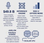
With over 500 million smart speakers already in homes and a voice assistant application market projected to grow from $6.3 billion in 2025 to $49.82 billion by 2033, the future of voice computing is moving from cloud to edge.[2] On-device processing for wake-word detection, keyword spotting, and natural language understanding is becoming the standard.
This shift to local inference brings critical benefits: improved responsiveness, enhanced user privacy, and lower ongoing cloud infrastructure costs. [3] But it also creates a new dilemma for chip architects: how to bring data center-grade inference capability into a consumer SoC with a bill of materials often constrained to under $3–$10 per unit, depending on the device class. [4]
That challenge is reshaping SoC architecture. [5] These devices must now deliver real-time performance, neural inference, and ultra-low power consumption in thermal and cost envelopes more typical of smart remotes than smartphones.
A $10–$15 Billion Opportunity
While high-end smartphones can afford complex neural engines, the majority of voice-enabled products—like thermostats, remotes, and earbuds—cannot. These devices require purpose-built, cost-efficient SoCs priced in the $3–$10 range. According to Market.us, the edge AI integrated circuits (ICs) market is projected to grow from $17.3 billion in 2024 to $340.2 billion by 2034, with over 70% of that value attributed to inference tasks—including those performed by voice-optimized SoCs for wake-word detection, on-device speech recognition, and natural language processing (NLP). [6]
The SoC as the Voice Compute Backbone
To support always-on voice capabilities, SoCs must become the central compute engine inside embedded devices. These chips must continuously listen for user input while consuming only milliwatts of power. They need to execute inference tasks, such as wake-word recognition and intent parsing, in less than 100 milliseconds. They also must interface seamlessly with control logic and input/output systems, all while adhering to strict cost constraints—typically with a bill of materials under $10.
This shift reflects a broader trend toward embedding intelligence directly into the fabric of everyday products. Consumers don’t expect to buy separate “voice assistants.” They expect voice interaction to be built in and invisible—like buttons or touchscreens once were.
SoC Design for Voice as a Feature
Meeting these requirements calls for a hybrid SoC architecture. This includes a scalar processor—typically ARM or RISC-V—for managing operating system tasks and control logic. [7] A vector or matrix engine handles the heavy lifting of AI tasks such as wake-word detection and intent parsing. To ensure efficiency and predictability, the architecture incorporates a deterministic scheduling model that avoids the power and verification challenges of speculative execution.
This combination delivers advanced AI workloads efficiently—without the thermal and architectural overhead of traditional, general-purpose designs.
In this new generation of voice-enabled devices, the vector-matrix processor is not just more valuable than the scalar unit—it is the performance and power bottleneck driver. Inference workloads such as wake-word detection, keyword spotting, noise suppression, and intent parsing now account for over 80% of total compute cycles and up to 90% of dynamic power consumption in voice-capable SoCs.
The AI engine typically occupies 2–3× the silicon area of the scalar core, yet delivers orders of magnitude higher throughput per watt. [8]
A Next-Generation SoC Axelon Interface Integrates Scalar & Vector
Simplex Micro’s Axelon architecture embodies this next-gen approach. It provides a flexible CPU interface to integrate a scalar core (ARM or RISC-V) with a RISC-V Vector engine, while introducing a novel time-based execution model. This deterministic scheduler eliminates the complexity of speculative execution—a common technique in general-purpose CPUs that adds power and verification overhead—delivering consistent, low-latency AI performance.
ARM vs. RISC-V: The Battle for AI Acceleration
ARM continues to dominate the scalar core market and will remain a cornerstone for control logic. However, when it comes to AI acceleration, ARM’s Neon SIMD architecture is limited in vector width, scalability, and power efficiency.
In contrast, RISC-V—with its open architecture, variable-length vector support, and extensibility for custom AI instructions—offers a more scalable and energy-efficient foundation for edge inference. These advantages are driving its adoption in hybrid SoCs optimized for embedded voice.
Conclusion: Voice Is Infrastructure, Not a Product
We are witnessing a silent revolution in silicon. Voice is no longer a standalone product category—it’s infrastructure. A baseline feature, embedded directly into the interface layer of modern devices.
The companies designing the SoCs that enable this transition will define the next generation of user interaction. ARM will remain essential for control, but the competitive frontier is in AI acceleration. Here, RISC-V vector processors—especially when paired with deterministic execution models like Simplex Micro’s Axelon—are poised to lead. Quietly and efficiently, they are powering the age of voice as a feature.
References
[1] Remesh. (2022). 5 Ways Voice Recognition Technology Sways Consumer Buying Behavior. https://www.remesh.ai/resources/voice-recognition-technology-consumer-buying-behavior
[2] MarketsandMarkets. (2024). Voice Assistant Application Market Size. https://www.marketsandmarkets.com/Market-Reports/voice-assistant-application-market-1235279.html
[3] ARM. (2025). Silicon Reimagined Report. Chapter 2: AI at the Edge. https://www.arm.com/company/newsroom
[4] ARM. (2025). Silicon Reimagined Report. Chapter 2: Power-efficiency limits. https://www.arm.com/company/newsroom
[5] ARM. (2025). Silicon Reimagined Report. Chapter 1: Custom silicon trends. https://www.arm.com/company/newsroom
[6] Global Edge AI ICs Market Size, Share, Statistics Analysis Report By Chipset https://market.us/report/edge-ai-ics-market/
[7] ARM. (2025). Silicon Reimagined Report. Chapter 2: Vector/matrix specialization. https://www.arm.com/company/newsroom
[8] Patel, D. (2022). Apple M2 Die Shot and Architecture Analysis – Big Cost Increase for Minor Performance Gains. SemiAnalysis. https://www.semianalysis.com/p/apple-m2-die-shot-and-architecture
Also Read:
S2C: Empowering Smarter Futures with Arm-Based Solutions
SystemReady Certified: Ensuring Effortless Out-of-the-Box Arm Processor Deployments
The RISC-V and Open-Source Functional Verification Challenge