As the percentage of pre-configured IP increases in semiconductors, so design teams are able to reduce design cycle times. But one of the challenges for design teams is the inability to quickly and easily find IP because it’s incorrectly classified, sat in a designer’s home directory, or it’s been put into the ‘repository’ by an IP developer and someone forgot to update the spreadsheet to notify the design team that it’s available.
These challenges of finding the right “needle in the IP haystack” introduces delays to achieving design closure that run into millions of dollars of lost opportunity costs.
It sounds far fetched that in this day and age companies would use a spreadsheet to track IP, but many semiconductor companies do not have a specialized IP management solution; instead they use a PLM or ERP system like Oracle – or they use an in-house/home grown system that needs constant enhancement and maintenance by a small army of developers.
The result of these ‘legacy’ processes and solutions is that design teams spend unnecessary time and energy trying to find the right version of the right IP for their design. Whether internally developed or externally procured, the information about all of the IP in an enterprise needs to be accessible to those who need to find and qualify that it’s the required IP. It also needs to be hidden or non-discoverable to those who don’t need to see it.
Consensia, a channel partner of Dassault Systèmes, will be holding a webinar (moderated by me) later this month to demonstrate how DelphIP helps its customers’ IP consumers quickly and easily find the IP they need to add to their Bill of IP/SOC BOM. Consensia’s description of IP is anything that includes software, hardware, firmware or documentation.
DelphIP is an IP lifecycle management solution. It is based on the Dassault Systèmes ENOVIA platform, so it understands semiconductor nomenclature like foundries, process nodes, and other attributes that IP developers and consumers use to create or search for IP based. These attributes are added when the IP is created or goes into the repository, so it’s easy to track it through it’s lifecycle.
WEBINAR REGISTRATION Tuesday, November 28, 2017 8:00am PT – 9:00am PT
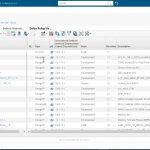
During the webinar, Consensia will demonstrate how design team members can search for, and easily locate, IP that meets their exact requirements – both internally developed or externally procured IP.
In an ideal world, IP would be developed and validated before a new design start commences. But in reality, IP is often developed in parallel with the chip design. DelphIP enables designers to see progress of IP that is being internally developed, as well as being notified when it has been published internally.
Consensia says that some of their customers have also benefitted from their Issue & Defect functionality. This allows ASIC/SOC design leads to report issues, have them assessed by the developer (or external vendor) and notified of the status of the IP so that they can get a roll up, hierarchical view of all of the defects in an SOC, something that the bug reporting tools don’t typically provide.
Consensia will also show something called collaborative workspaces which is a secure area used by customers working with external joint development partners. It enables semiconductor or IP companies to provide configurable access to specific IP with their partners. This accelerates the design process by giving visibility to specific IP on which they may want to undertake specific IP lifecycle management functions without compromising the security of other IP data.
The webinar should be an interesting insight into how IP lifecycle management is undertaken by some of the companies that use DelphIP. Again, you can register for Consensia’s webinar here. I hope to see you there.