Taiwan is roughly 1.5 hours away from China by ferry and even less by faster naval vessel’s. Many years ago when China was flying missiles over the rogue , runaway nation and we wrote about the risk to the PC industry.
Sometimes we get to see, up close, leaders who make a truly enormous contribution to society. Dr. Sunlin Chou was one such leader and I was a fortunate fellow traveler. Sunlin led the exponential rise of transistors for 35 years, accelerating the waves of revolutionary digital technologies serving humanity.
Fifty years have passed since Sunlin entered the electronics industry in 1968. At that time, the industry was adding about 1 transistor every year to the service of every human on earth. By the end of Sunlin’s career in 2005, the industry was giving 7 billion transistors every year to each of us. Today, you and I are receiving well over 50 billion transistors each.
Do you know where all of yours are? I don’t either, but I know that my transistors live just about everywhere. They wiggle on and off at speeds unimaginable, to support my everyday needs.
Sunlin had the fortune of joining this transistor exponential in its infancy. The exponential is made up of waves of transistor manufacturing technologies, each bigger, better and steeper than the previous wave. Bigger, because each wave made exponentially more transistors than the previous wave. Better, because we made each transistor faster, less power hungry and half the size compared to its predecessor. And steeper, because we ramped the production of transistors faster than we did in the previous wave. If a wave was not bigger, better, steeper and on time, there was a stiff economic penalty to be paid.
How do you ride such exponential waves consistently and elegantly over decades?
The answer is found in the architecture and disciplined use of an organizational machine Sunlin invented. The purpose of the machine was to synchronize the aspiration, the energies and the output of thousands of people riding the wave from across the globe and, over several years. The result was one spectacular exponential wave after another, of transistors penetrating our lives at ever increasing rates.
Sunlin’s synchronizing machine was as simple as it was impactful. At its very core was the concept of synchronizing (synch) points. These were well-defined and well-marked stakes in the ground which had to be reached predictably. Sunlin chose the manufacturing ramp of every wave as its master synch point and he mandated its placement on a 2-year cycle between waves (2-year rhythm maximizes the economic value of riding transistor waves). All activity across Intel and the semiconductor ecosystem was pipelined to synchronize at that synch point.
A key architectural feature of Sunlin’s machine was the partitioning of the multi-year pipeline into Research, Development and Manufacturing (RDM) phases. The Research phase pruned technology options to carry forward into Development. The Development phase defined the new wave’s specifications and developed manufacturable ICs made up of transistors. And the Manufacturing phase ramped and maintained transistor production for the rest of the wave’s life. Each phase was well defined in terms of deliverables and hand-off points which served as intermediate synch points in the pipeline.
The structural integrity of the machine was in the disciplined use of built-in risk management features.
An example is Sunlin’s “COPY EXACTLY!” (“CE!”) doctrine. In the manufacturing phase of the pipeline, multiple factories were needed to support the manufacturing volumes of transistors in a wave. Sunlin programmed the machine to replicate technologies in each fab, one after the other, in order to ensure an un-interrupted flow of increasing output during, and after, the rise of the wave. So detailed were the copy spreadsheets, and so strong was the intent to copy exactly, that we never used the phrase “CE!” without the exclamation point.
As a second example, Sunlin designed large overlaps in the transitions from R to D and D to M in the RDM pipeline. At these transitions, some wave riders stepped off and others stepped on to take the pipeline further. To ensure un-interrupted flow of work through these handoff points, Sunlin sent developers upstream to work with researchers to finish, and select, research streams for the development phase. He sent developers into the manufacturing phase by making them responsible for the first manufacturing ramp of the wave. And, he sent manufacturers to work alongside developers to learn, finish and copy the technology for subsequent factory ramps of the wave.
Yet another example is the way Sunlin limited variables in the development phase of the RDM pipeline. Manufacturing technology in a wave was expected to re-use more than 80% of the equipment of the prior wave. This change control limited exposure. He also imposed a restriction on the design of the chip leading the wave. It was expected to reuse the architecture from the prior generation with changes limited to those required for manufacturing. This controlled the risk that came from debugging simultaneous changes in design and manufacturing of the chip leading the wave, and came to be known as the Intel TICK-TOCK development model.
A networked hierarchy of synch meetings served as the synchronizing machine’s operating system. These meetings included multiple cross-functional engineers who followed time tested dashboards to keep the wave’s relevant synch points front and center. Sunlin attended the highest synchronization meetings on a regular basis. One of them was a bi-annual meet where he interacted with hundreds of senior engineers representing hundreds of organizations and disciplines, gathered to take a holistic view of the wave.
When Sunlin passed on in December 2018, there was an outpouring of sentiment from those whose lives he had touched: “a brilliant mind”, “a well-balanced man”, “a gentle soul”, “a humble man”, “grounded in competence”, “integrity and class”, “an authentic, empathetic manager”, “a pioneer”, “a conceptual thinker”, “an inspiration to all”, and “a legend!”.
Sunlin was all that and more. Sunlin exemplified the power of architectural integrity in conceptual thinking. He showed us how it can serve as a solid foundation for journeys unimaginable.
Semiconductor chip package technologies have evolved throughout the years to the point where hundreds of package types are available today.
Most applications will require the more general, single-element packaging for integrated circuits and the other components such as resistors, capacitators, antenna etc. However, as the semiconductor industry develops smaller and more powerful devices, a ‘system in package’ (SiP) type of solution is becoming the preferred choice, where all elements are placed into a single package or module.
While package types can be easily categorized into lead-frame, substrate or wafer-level packages, selecting a package that will suit all your requirements is a bit more complex and requires evaluating and balancing the application needs. To make the right choice, you must understand the effects of multiple parameters like thermal requirements, power, connectivity, environmental conditions, PCB assembly capability and of course, cost.
Here are some key requirements that you should evaluate to select a suitable packaging technology. For the full-length discussion of requirements, please see our white paper, The Ultimate Guide for Selecting an ASIC Package.
Your target application is the primary driver dictating your package selection. Is your application a low-cost consumer device or a high-cost industrial ASIC? Will it be running in a hot environment? Will you develop a System on Chip or will your ASIC be a key component within the system? Such questions will help you decide on the type of packaging – whether you can you use wafer-level or chip-size package, or can standard, more readily available BGA or QFN type packaging be more relevant.
Application performance requirements and the corresponding packaging options can be broadly categorized into three groups:
High-end application requirements are often related to high-speed, high-power chips that have a large number of connections (high pin-out). These devices will require advanced packaging requirements to match the needs of small pad pitch, high-speed signals and decoupling, that can be achieved with the FC-BGA (flip chip BGA), or newer packaging like embedded Wafer Level Ball Grid Array (eWLB).
The Mid-range group typically require packaging that can address thermal enhancements and employ cost-effective plastic packaging technologies – often in the BGA and QFN type approach. At the higher end of this group are chip level and wafer level packaging, suitable for system in package and/or multi-chip module packaging.
The Entry level group includes high-volume applications where cost is the main driver rather than performance. Devices for notebook and mobile applications, for example, will generally require small size wafer level and chip size packaging.
The number and location of input and output connections of any device are key factors to be considered when determining the package requirement.
High pin count. If you’re looking at a very high pin-count, say 1000 pin package, then your best option may be a standard BGA package, which offers such I/O capability as overall package size can go up to 50-60 mm square.
Low pin count. For a low pint count, say 50 pins your choice would probably be a QFN or WLCSP package. However, a WLCSP will have limitations for heat dissipation within the package. In cases where there is heat generation (e.g., fast switching) or need for good signal grounding, then a QFN is the better package choice, due to the ‘built-in’ metal base pad.
Layout. Another parameter is the location of I/Os. If the I/Os are on the periphery around the die, then wire bonding is quick, easy and reliable provided there is enough surface area in the die and package pads for this. If the I/Os are spread across the surface of the chip in different areas, so that wire bonding out from the center of the chip is difficult, then flip chip packaging offers a direct attach approach onto the substrate of the package, which is usually a multi-layer PCB, and there would be no concerns about the die overlapping.
Thermal management is a key packaging factor for optimizing chip performance. A BGA package, for example, can often offer lower cost/improved thermal management solutions within the package because of its size, as it has a larger area available to dissipate the heat. The smaller real-estate chips can be more expensive in terms of the thermal management solution, requiring an external heatsink or other cooling options.
BGA packages have options with both thermal pads, such as conductive vias or inbuilt metal base plates that can enable adequate heat management. Some options of thermally enhanced BGA packages can have a metal cap built onto them that establishes a thermal conduction path between the IC device and the metal cap, which provides good heat dissipation.
QFN packages are designed such that they have a solid metal die pad as the base of the package, to which the die is bonded. This enables very good heat dissipation from the silicon die through to the PCB.
Die attach materials. Bonding the chip to the substrate with a thermal conductive adhesive like Sliver filled Epoxy, rather than plain epoxy, will help remove the heat. In addition, newer technologies are available like Silver sinter technology – an interconnection method with high operating temperature, high thermal and electrical conductivity. These materials typically work well in QFN packages, but are not as effective in BGA packages, due to the package construction.
Chip size and wafer-level packaging. Thermal management in these packages is primarily done on the back of the chip, or in chip size package, on the exposed top-side of the chip.
RF, wireless and high-speed digital designs have specific requirements that affect package selection. The signal speed and the frequencies can be significantly degraded by the parametric effects of the interconnections within the package.
Wire bond vs. flip chip. In RF devices, key design considerations involve inductance, capacitance and resistance, which are affected by the speed of the signals travelling in and out of the device. These issues also impact package selection, primarily between flip chip and wire bond interconnections. Flip chip will provide better RF Performance and enable reaching higher frequencies with lower inductance. Wire bonds, on the other hand, can add a randomly-variable inductance at each RF input or output at higher frequencies.
Package layout. At RF frequencies, signals travel along the surface rather than in the conductor. Hence, the way in which the package is assembled has an important effect on the device. For example, high-speed amplifier chips, RF transistors, and diodes often cannot be put into a “standard” plastic package, as the encapsulation materials affect the speed in which the chip operates. Consequently, such chips should go into a cavity QFN or BGA package.
High frequency signals (1 GHz and above) are likely to require the layout of the interconnections to have isolated signal paths, known as “ground signal ground” interconnect. Here the requirement of two ground connections for every signal i/o will impact the package size and layout.
Additionally, with high-speed ASICs, the signal levels and timing will be affected by the length of the conductor that they travel along. For example, if you are using a BGA package and you have a longer lead to one point and a shorter lead to the next, you will have timing differences on the signal. This must be overcome by putting more consideration into the initial design of the package substrate to accommodate the high-speed RF devices.
BGA substrate dielectric materials are also a key factor in RF chips. For example, a high-performance liquid polymer substrate, like Rogers laminate, is better suited than the standard FR4 PCB material for use as the substrate for BGA packages used for RF designs.
To read a full-length discussion of packaging requirements, please see our white paper, The Ultimate Guide for Selecting an ASIC Package
Author
Written by Sharon Akler.
Sharon has a background in technology and innovation and more than 20 years of experience in global companies and startups. At DELTA, Sharon is looking after sales in Europe covering ASIC supply chain services.
About DELTA Microelectronics
With over 25 years of experience, DELTA Microelectronics is a European leader in ASIC services for the semiconductor industry. DELTA’s comprehensive services include ASIC design, layout, test development, wafer supply, production testing, package development and assembly, components supply, logistics and supply chain management. DELTA’s development and production facilities are based in Denmark and the UK, with service partners in Europe and Asia. For more information, visit asic.madebydelta.com
The “20 Questions with John East” series continues
I started out as a supervisor in the wafer sort and class area. Today you’d call those probe and final test. My first boss, a man named Les Faerber who I had never met, met me in the lobby, got a smock for me, took me into the test area and introduced me to the ladies (All the operators were women in those days). I had no idea what they were doing. I didn’t even know that integrated circuits were made on wafers much less that those wafers needed to be “sorted”. Then he said, “I’ve got a meeting. Gotta go.” And he left. Terrifying!!! I was standing there trying to act as though I knew what was going on (I didn’t have a clue) when a really aggressive guy with a British accent came charging in. “Who’s the supervisor here?!!!” “Why isn’t the waterfall running?!!!” And, of course I thought to myself, “Who is this guy? What’s a waterfall? What am I doing here?!!!” It was John Carey. He was the operations manager for all integrated circuits. He wasn’t a patient man! He scared me to death the first few times I dealt with him, but after a while I grew fond of him. That was a shame, because very soon he would fall victim to “Off with their heads”.
That first afternoon a technician named Jack Drury was trying to teach me a little of what we were doing in wafer sort and class. I’m sure it crossed his mind to wonder why an experienced technician like him was now working for an acne-faced college kid who had no clue about anything that mattered, but he tried to be helpful. We stood in front of a prober and watched a wafer being tested (sorted). I was impressed with the wafers. “Wow — you can make hundreds of these IC things at a time. That’s cool!” Each wafer had a few hundred “dice” on it. Our job was to test them and identify the good ones. (At Fairchild, we called the individual ICs “dice”. A single IC chip was a “die”. At most other companies they called them “chips”.) The prober would stop on each die. The tester would flash cool looking lights on and off for a few seconds, and then a small mechanical arm would put a little red dot on the die. It seemed pretty efficient. I asked Jack what the little red dot was for. He said, “Oh. That’s the inker. We put a red ink dot on each die that doesn’t work right.”
Me: “Oh. I see. That’s cool. But – every one of the dice has a little red dot.”
Jack: “So?”
Me: “So all of these wafers that were already sorted have red dot’s on all their dice as well”.
Jack: “What’s your point?
Me: “Duh”
Jack: “That’s a TTL lot. The lot is zeroing out. Big deal. That happens all the time to TTL.”
I think it was a 50 wafer lot. Each wafer probably had 500 dice on it. So — the first 25,000 integrated circuits that I ever saw were all thrown out. Nobody seemed to care.
Maybe that’s what led up to “Off with their heads.”?
What was “Off with their heads?” Well, as I described in “Day One”, many heads had already rolled after Hogan’s Heroes arrived but before I got there. I heard some people saying good things about a man named Tom Bay. I asked what job he was in. “Oh. He’s gone. Fired a month ago.” Tom was formerly the VP of marketing and, as far as I knew, the first victim of “Off with their heads!” Then, shortly after I got there, the VP of sales, Jerry Sanders, was fired. Jerry, of course, then founded AMD and went on to a great career. Then, John Carey (The guy who wanted the waterfall running) was fired. He went on to be the CEO of IDT. Carey was replaced by a man named John Husher, but he was in and out of there so fast that I never got to meet him. Bob Noyce, Gordon Moore, and Andy Grove had left to form Intel. Charlie Sporck gone too. Charlie had left to be CEO of National Semiconductor. Charlie took Floyd Kwamme, Don Valentine, and Pierre Lamond (all of eventual Venture Capital fame) with him. Gene Kleiner was gone as well. Gene was one of the traitorous eight but went on to be the head of what is probably the most famous Venture Capital firm of all – Kleiner Perkins. In fact, every one of the Traitorous Eight founders left under various circumstances. There were people disappearing left and right. Sometimes you didn’t know if they were fired or if they just quit. One morning you’d come in and they were gone. Why? Where? How? Who knew? Who was doing all this firing? Who knew? It seemed as though a Vice President and Hogan’s Hero named Gene Blanchette was at the root of a lot of it, but before long, Blanchette himself disappeared. I don’t remember how or why. I probably never knew. And then, in 1974 the coup de grace. Hogan himself was gone. There was a popular song in 1967. “White Rabbit” by The Jefferson Airplane. Its lyrics put a new spin on Alice in Wonderland. — “And the red queen, ‘Off with their heads!’ ” — Wow. That’s too close for comfort around here!!!
Have I rediscovered Alice in Wonderland? Did I go down the rabbit hole? And where did I put that hookah?
See the entire John East series HERE.
Pictured: Jerry Sanders at the 1968 Fairchild Hawaii Sales conference. Jerry had just been informed that Les Hogan had been hired to be his boss. Jerry sent this picture to Les. Three months later, Les fired Jerry.
I assume you know the Geoffrey Moore “crossing the chasm” concept, jumping from early stage enthusiasts trying your product because they’ll try anything new, to expanding to a mainstream and intrinsically more critical audience – a much tougher proposition. I’d argue there may be more than one of these transitions in the life of a new venture, the first of which can be adoption by a mainstream partner as a part of one of their solutions.
Tortuga, a company that specializes in hardware threat detection and prevention in hardware plus software systems, already had important academic credibility, being birthed from hardware security groups in UCSD and UCSB. They have clients in the semiconductor, aerospace and defense industries, they’re on their second SBIR (small business innovation research) grant, they’ve raised seed funding and last year they received a contract from DARPA to develop new security solutions. All good stuff but feeling like it’s still mostly on the left side of the chasm. Where was mainstream semiconductor support going to come from?
In answer to that question, Tortuga announced just a few weeks ago a partnership with Synopsys. This offers a security verification solution for SoC designs built around the Synopsys DesignWare ARC processor IP and Tortuga’s Radix-S security verification software. Does that mean Synopsys needed extra help to ensure the security of their ARC solutions? Not at all. The unavoidable problem in developing security solutions around any IP is that they depend on the SoC developer not making mistakes in integration. One such example could be a mapping error for the the boundary between secure and insecure operation. Another could be allowing access to secure registers when a debug port has not been correctly disabled. Checking you didn’t make mistakes can become pretty complex, not always easily reducible to assertion VIPs. This is particularly challenging since misbehavior in these cases may be revealed only in interaction between hardware and software over many cycles.
The Tortuga approach to analyzing these integration problems is quite interesting, evolving (as I understand it) from a method called gate-level information flow tracking, coupled with a threat-model in the form of assertions against this analysis. This compiles into verification logic which runs together with your DUT and whatever verification workloads you normally run to check for potential threats as defined by these assertions. I’m told that as long as your verification regressions deliver good general coverage (they’d better at some point), you will have good confidence that these security threats will also have been covered.
Jonny Valamehr (COO at Tortuga) tells me that they and Synopsys have worked together to define a comprehensive set of threat assertions to cover many integration needs. Since an ARC core provides some level of configurability, Jonny said some aspects of the threat model may also need to be configured by the integrator to cover these cases. But I got the impression this isn’t very hard. From what I have seen, threat assertions don’t look so different from SVA assertions, though they express information about paths for assets to flow through the design, rather than logic behaviors. If you’re responsible for security, learning this assertion language doesn’t look like a big barrier.
Jonny tells me that today you buy your ARC core from Synopsys and you buy the Radix-S software from Tortuga. Synopsys and Tortuga have done the development to ensure the technical part of this flow works seamlessly. Making the business flow seamless is still in discussion. Nevertheless, good job Tortuga on taking this important step. You can learn more about Radix-S HERE.
We already know that IP-Xact is extremely useful for managing IP and SOC design specifications, yet it may come as a surprise to learn that it also can be used to form the basis of a power flow too. There are design tools that read UPF to help implement and verify designs, however it can be extremely useful to understand the interplay between the power intent and the fully elaborated design early in the flow.
First off, let’s back up and talk about how designs with multiple power and voltage domains are specified. In theory, and often in practice, the RTL for a design provides no guidance for power domains or voltage domains. Of course, there may be a mode controller in the RTL, or the design might be completely power agnostic. Certainly, the RTL will not have information about signal levels between blocks or information about implementation of the power nets. This is where UPF comes in.
UPF works in conjunction with the RTL to fully define the details of the supply connections and the signals that cross domains. Power and ground nets may be connected or disconnected to save power in certain operating modes. Signals may need level shifting, and isolation or retention when blocks switch off. UPF is based on the logical hierarchy, which is available in a fully elaborated design.
Writing UPF directly can be a daunting task. Magillem, a leading provider of IP-XACT solutions, saw a way that IP-XACT and power intent can be combined to make specification of power intent easier, and used to check for issues before moving into the implementation phase. IP-XACT already provides a way to create, manage and elaborate an RTL design, by capturing information for the hierarchy, block interfaces, buses and signals. Magillem realized that tabular input through csv files is an ideal way to specify power domains, voltage domains, power states, isolation rules and level shifter rules. These can be applied to the fully elaborated design to create a complete specification.
Using this flow mismatches between the power intent and the design can be easily detected. Magillem has also implemented checkers for missing level and isolation elements. Propagated power properties are reported, as well as any warning or errors. Their IP-XACT power flow provides verbose reports to provide easy traceability. Magillem’s power flow outputs a domain based virtual hierarchy and offers visualization so that it is easy to understand the domain partitioning. Then in the final step it outputs UPF 2.0 for use downstream in the design flow.
Mistakes in specifying power intent can be fatal and navigating through reams of UPF looking for issues can be frustrating. Magillem makes the entire process easier by letting the designer work on the fully elaborated design and get a clear picture of what domain each instance is in. Magillem’s power flow can ensure that there are no missing level shifters. It also can help ensure that level shifters, isolation and retention are in all the necessary locations. While UPF provides a nice partitioning between design and power specification, it’s good to know that Magillem’s power flow offers a high-level solution for integrating and verifying them early in the design process.
Machine learning (ML) is already making its way into EDA tools and flows, but the majority of announcements have been around implementation, especially in guiding toward improved timing and area. This is a pretty obvious place to start; ML is in one sense an optimization technique, trained on prior examples, which should be able to provide further PPA optimization over traditional methods. Conversely, few announcements have been made about ML applications for (functional) verification, perhaps because incremental optimization angles for verification aren’t quite so self-evident, beyond general assertions that “something” ought to be possible. I don’t doubt this situation will change; creative verification tool/flow makers will find ways to apply ML in ways that aren’t so obvious.
That this is already possible is clear in advances Cadence have made in their new, smart JasperGold Formal Verification Platform. I suspect progress started here first because formal platforms have some things in common with implementation platforms – multiple engines to accomplish a goal in different ways and lots of knobs to control how those engines work. The JasperGold Smart Proof technology exploits these two factors directly. For optimization within an engine (Anirudh calls this ML-inside), the tool provides training data built on 500+ customer designs to parameterize that solver for optimum performance.
There’s also an important optimization in solving across engines. It is common in formal verification to use more than one engine to attempt a problem since engines have different strengths playing to different classes of problem. You could first try one approach and if that doesn’t succeed after some number of cycles, switch to a different approach. But that’s old-school. A newer approach depends on orchestration – a semi-automated method to launch multiple runs, each with a different strategy – to find a best-case outcome as quickly as possible. ML-based orchestration takes this one step further, learning again from runs on those 500+ test cases, how best to optimize that orchestration (Anirudh calls this ML-outside). Orchestration starts with out-of-the-box supervised learning, giving you value from day 1 then adding on-going proof-profiling based on your usage to further improve performance.
What different does this make? Pete Hardee (Dir Product Management at Cadence) tells me that across a representative set of designs, they are seeing ~10X faster properties proven per second, and on a set of known “hard” designs in which it is difficult to get to proofs on many properties, they were able to reduce inconclusive proofs from 46% to 29%.
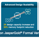
When you’re king of the hill, you don’t want to rest on just one advance. Pete tells me this new release also compiles 2X faster and in a 2X smaller memory footprint. This has been measured on multiple designs, up to 100M+ gates. Now wait a minute – this is formal, the technology that only works with small designs, right? Pete told me that yes, you’re ultimately going to want to abstract or otherwise reduce to get to a manageable problem for proving, but why force you to do that before you even readin the design? All those steps, including useful analysis (like cone-of-influence) can be done on the build image and you can let the tool take care of the heavy lifting in applying abstraction, etc.
Last and certainly not least, they have put significant work in integrating and simplifying the analysis GUI with aim to support signoff-quality coverage. I’ve talked before how you can integrate formal coverage with dynamic coverage through vManager. They’ve added an all-new coverage analysis GUI in support of the formal side of this, tracking coverage runs versus proof runs, providing easily accessible information on dead-code and over-constraints, a unified view of proof-core and cone-of-influence coverage and a new formal coverage metric looking at both stimuli and checkers.
Not only is Cadence a clear leader in formal, it looks like they’re working hard to stay there. Check out the new updates HERE.
As a testament to the technology advances developed and implemented into Empyrean ALPS™ by the engineering team, the product has seen a steady growth in the adoption by users. In addition, hearing directly from the users at DAC 2018 turned out to be an all-around success for the product as well as the product team to see ALPS beating other established parallel SPICE simulators in performance while maintaining the same accuracy. When good work is recognized, engineering motivation shoots up and greater outcomes begin to happen. You can see that in the form of GPU-accelerated ALPS at the 56th DAC. The recent announcement of Empyrean ALPS being voted by users at DAC 2018 as “Best of 2018 DAC” in SPICE simulation is yet another recognition of the product and the product team. The outcome of all the above is the introduction of a GPU-accelerated ALPS at the upcoming 56th DAC at Las Vegas, Nevada.
SPICE Simulation Challenges
In any typical SPICE simulation run, close to 90% of the time is spent on two operations: Device model evaluation and matrix solving. Empyrean’s engineering team came up with a novel algorithm, the Smart Matrix Solver (SMS) to address matrix solving. A multi-threaded, CPU-based architecture and the Smart Matrix Solver empowered ALPS to run not only faster, but also maintain the same accuracy with SPICE. The speedups were to the tune of 3X to 8X over other simulators and without the need for accuracy trade-off using model simplification of RC reduction techniques on analog and mixed-signal designs, especially with post-layout simulations runs where the parasitics add up to tens of millions of elements, impacting performance and accuracy. Click here for user feedback on ALPS. Join us at the 56th DAC in Las Vegas, Nevada at the Empyrean booth #651 to learn about Empyrean ALPS.
Stepping Up with GPU-Based Architecture
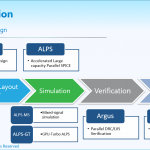
The product success further motivated the engineering team at Empyrean which had been actively working on a GPU-based implementation. With a GPU-based architecture, they were able to cleverly direct and massively parallelize the two time-consuming operations, device model evaluation and matrix solving to the GPUs with 1000s of cores, while keeping rest of the simulation operations on the CPU. Working closely with some key customers, the most common hardware, NVIDIA’s Tesla V100 was selected as the platform to use. NVIDIA’s CUDA™ solver that came with V100 was fast but not fast enough for SPICE runs. The team enhanced the Smart Matrix Solver by optimizing it for GPUs to achieve greater simulation performance while keeping accuracy. Empyrean will be talking to early customers for this product, called Empyrean ALPS-GT™ at the suite at DAC.
AI -Powered IP Timing Arc Prediction
Further strengthening its position in the AMS design, Empyrean will be showcasing a new AI -powered timing arc prediction especially for analog and mixed signal IP and library circuits. This is a capability that Empyrean developed by working closely with a few key customers. A joint paper with NVIDIA is being presented on this at the Designer Track session at DAC 56 (Paper ID:268-WC54).
Timing arc prediction for an analog or AMS circuit is relatively difficult, and with the AMS content continuously increasing in SoCs, the need for accurate prediction is critically important and can often lead to costly silicon failures. Please stop by the Empyrean booth (#651) to learn about this capability in Empyrean Qualib-AI™ product and how it is being applied to designs.
The most recent blog on SemiWiki by Daniel Payne goes into more details on the GPU-accelerated SPICE and the AI-powered Qualib.
Better SoC Design, Debug and Analysis
Empyrean’s claim to fame in the SoC market was with Empyrean X-Top™, a comprehensive timing eco analysis and fixing capability, which was first adopted by Marvell, and later making it a required sign-off tool in their flow. X-Top is an ultra large capacity placement and routing aware timing eco engine with automated and interactive eco capabilities. Today’s complex multi-voltage domain designs with simultaneous multi-mode multi-corner (MMMC) optimization are ideal candidates for this tool. Stop by Empyrean’s booth at DAC to check out X-Top and how it is in the tape-out flow of many companies.
Empyrean’s ClockExplorer™ is another valuable solution for diagnosis and analysis of clock circuits in today’s designs with complex clock domains. Its powerful visual diagnosis capabilities provide the back-end implementation teams the ability to easily visualize clock networks and implement it as intended by the front-end design team, thereby reducing unnecessary silicon iterations. Stop by the Empyrean booth to check out ClockExplorer.
Skipper™ has been a great add-on to the SoC design flow at many companies to analyze very large pre and post-silicon layout database for anything from DRC/LVS debug to failure analysis. Its very fast layout bring-up, IP merging and post-silicon FIB processing along with powerful diagnosis and analysis capabilities make it an attractive add-on to many SoC design flows. Skipper was also recognized by users at DAC 2018 as “Best of 2018 DAC.” Click here for the user feedback on Skipper. Stop by the Empyrean booth to check out Skipper.
About Empyrean Software
Founded in 2009, Empyrean Software is an Electronic Design Automation (EDA) and intellectual property (IP) technology leader in delivering fast and true physically aware, design closure and optimization solutions for timing, clock and power of system on chip (SoCs). The company also offers a high-performance accurate circuit simulator and is an analog IP and fast SerDes IP provider. For details, go to Empyrean Software.
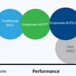
I first started using a SPICE circuit simulator in 1978 while at Intel and have followed that market ever since then. Back at DAC in 2012 I first heard of a Chinese EDA company called IC Scape with a SPICE circuit simulator called Aeolus, so I blogged about it. Fast forward to 2019 and I heard from Ravi Ravikumar, a former co-worker from Viewlogic days in the 1990s and he was excited to talk about Empyrean, because they have the tools from IC Scape plus they’ve added even more EDA tools. You’ve probably heard of classic SPICE and the more modern Fast SPICE simulators, so the following chart shows where the Empyrean simulators fit into that space:
The ALPS acronym stands for: Accurate, Large capacity, Parallel, SPICE. The GT suffix stands for: GPU-Turbo. Other companies and Universities have attempted to use a GPU to speed up the matrix math used in SPICE, but none of them have had commercial success, until now. So, why would you employ a GPU for SPICE circuit simulation?
Empyrean ALPS-GT runs on the Nvidia Tesla V100, and it simply outperforms SPICE simulator running on an Intel Xeon 8180, for example. OK, that sounds attractive, but as an engineer I want to know how it operates under the hood. The matrix math library found in the CUDA library could be used for SPICE, but it’s not fast enough or efficient enough, so the team at Empyrean wrote their own matrix solver to run on the Nvidia GPU.
Comparing the Nvidia Tesla V100 versus an Intel Xeon 8180:
In benchmarks between the Nvidia CUDA matrix solver versus the Smart Matrix Solver from Empyrean, the new approach is 5.8X faster on average. Comparing a CPU with 16 cores versus 8 GPUs, the ALPS-GT simulator was 6.4 to 16.9X faster. So that’s how you make your GPU-based SPICE simulator faster than the competition, impressive.
DAC Designer Track
I hope that you can make it to DAC56 in Las Vegas, but if not I wanted to at least tell you something about a paper authored by Empyrean (An-Jui Shey, Jason Xing) and Nvidia (Eric Hsu, Ting Ku):
Qualib AI: Machine Learning Based Arc Prediction of Timing Model for AMS Design
For AMS timing models you can use the manual method of defining timing arcs, which is time consuming and error prone, or you can apply machine learning to find more timing arcs. Empyrean has a commercial tool called Qualib that is a library/IP QA and debugging platform, but the paper shows how they have extended that for Nvidia to make Qualib AI, which is not commercially available yet, so stay tuned.
Let me show you a couple of diagrams, the first one is an application flow for timing arc prediction, the second one is timing arc modeling and prediction algorithm:
What Nvidia found in using Qualib AI is that the tool:
Summary
The team at Empyrean has been busy creating a GPU-based SPICE circuit simulator and applying AI to complex IP blocks in order to shorten development times at Nvidia. They are certainly on my radar to keep a watch on, because if they can satisfy the leading-edge demands at Nvidia then they are definitely a contender for new EDA tool evaluations. Why use old technology, when something newer comes along?
Every morning I read the headlines from SemiWiki, CNN, LinkedIn and my Twitter feed, and it seems like every week that I read about another security breach that makes me wonder if anything online is secure. Companies try to harden their web sites, IT infrastructure and even their electronic products from being exploited or tampered with. Every article that you read about the IoT and connected devices is sure to mention security. Now let’s take the next step and say that you are designing a new SoC and intend to use hundreds of IP blocks, many from 3rd party vendors, so how do you know that each IP block will function properly and securely once integrated into a system?
I know that in the software world that we get new updates to improve the security of so many things, like: Operating Systems, desktop apps, mobile apps. Even my bike computer and cycling power meter have updates to fix bugs and make them more secure. Every semiconductor IP company has a process for making each IP block secure, but what about the entire industry?
Thankfully our industry has a well-known standards body, Accellera, and they have recently formed an IP Security Assurance Working Group.
Brent Sherman from Intel is the Chair, along with Mike Borza from Synopsys as the Vice Chair, so this looks like a solid start to tackle this concept of IP security across our semiconductor industry. You may even want to join this working group, so begin the process.
DAC 56 is coming up in June, so you should consider attending a luncheon and panel discussion on this timely topic of IP security assurance. The event is planned for Monday, June 3rd from Noon to 1:30PM in Room N246 in the Las Vegas Convention Center. It’s easy to register online here.
Accellera Chair Lu Dai will kick off the panel, and it should be lively and informative. The following speakers are panelists:
I’ve worked at companies with both Serge Leef and Andrew Dauman, so these panelists are smart, experienced and articulate on the topic of IP security.
Summary
Exploitable vulnerabilities can be mitigated in semiconductor IP, so Accellera is forging ahead with an IP Security Assurance Working Group to create a standard that our industry can define and follow. Visit their web site and plan to attend the DAC luncheon and panel discussion to learn and participate.
Accellera
Accellera Systems Initiative is an independent, not-for profit organization dedicated to create, support, promote, and advance system-level design, modeling, and verification standards for use by the worldwide electronics industry. We are composed of a broad range of members that fully support the work of our technical committee to develop technology standards that are balanced, open, and benefit the worldwide electronics industry. Leading companies and semiconductor manufacturers around the world are using our electronic design automation (EDA) and intellectual property (IP) standards in a wide range of projects in numerous application areas to develop consumer, mobile, wireless, automotive, and other “smart” electronic devices. Through an ongoing partnership with the IEEE, standards and technical implementations developed by Accellera Systems Initiative are contributed to the IEEE for formal standardization and ongoing governance.