One of the many benefits of blogging for SemiWiki is the free conference passes and buffet lunches, absolutely. IEDM is one of the more prestigious semiconductor conferences, now in its 65th year, is being held at the Hilton Hotel in San Francisco’s famed Union Square this week. This year more than 1,910 semiconductor professionals registered to see the 238 papers out of 613 submissions. The press lunch is a traditional conference event but IEDM did a very nice job this year so I will start our IEDM coverage here.
The conference theme this year is Innovative Devices for an Era of Connected Intelligence which sounds harmless enough if used for the greater good. The evil applications however are daunting if you think about it which I do constantly. Upon check-in we were given flash drives with all of the papers which will be great reading for the holidays.
The IEDM Publicity Chairs Rihito Kuroda, Tohoku University and Dina Triyoso, TEL Technology Center, America, did a brief overview of the conference followed by a Q&A session. The other conference chairs lunched with us as well which was great for networking.
From the presentation:
Reacurring themes
CMOS technology
3D Integration
Memories (NVM, MRAM, ReRAM, FeRAM)
Neuromorphic computing and devices
Novel materials and architectures
Power electronics
Negative capacitance devices – and applications
CMOS Technology
Session 3 – ALT – Monolithic 3D Integration and BEOL Transistors
Session 7 – MS – Physics of Ferroelectric and Negative Capacitance Devices
Session 11 – ALT – Gate-All-Around Device Technologies
Session 19 – ALT – BEOL and 3D Packaging Innovation
Session 29 – ALT – High Mobility Ge-Based Channel Devices
Session 36 – ALT – CMOS Platform Technologies
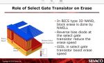
Memory Technology
Session 2 – MT– STT-MRAM
Session 15 – MT – Ferroelectrics
Session 22 – MT/EDT – Focus Session: Emerging AI Hardware
Session 28 – MT – Charge Based Memory and Emerging Memories
Session 35 – MT – Selectors and RRAM: Technology and Computing
Session 38 – MT – Memory for Neural Network
Related Session 7 – MS – Physics of Ferroelectric and Negative Capacitance Devices
Power Devices and Systems
Session 4 – PDS – Advances in GaN Power Devices and GaN Monolithic Integration
Session 12 – PDS – Advances in Silicon and Gallium Oxide Power Device Technologies
Session 20 – PDS – SiC Power Devices
We were not allowed to take pictures but I figured one of my lunch was okay. I get the no pictures thing to promote better content in the presentations but it is impossible to enforce and rampantly violated. The other issue brought up in the Q&A is the technical content. Several presentations by big name companies were flagged for empty content, ASML is a notorious offender. The conference organizers took our input gracefully but they should know IEDM is one of the best content conferences on the circuit.
Monday was memory day (MRAM), Don Draper will be covering that in detail. Scotten Jones has a handful of blogs in mind through the holidays so stay tuned to SemiWiki.com for semiconductor coverage by actual semiconductor professionals.
About IEDM
With a history stretching back more than 60 years, the IEEE International Electron Devices Meeting (IEDM) is the world’s pre-eminent forum for reporting technological breakthroughs in the areas of semiconductor and electronic device technology, design, manufacturing, physics, and modeling. IEDM is the flagship conference for nanometer-scale CMOS transistor technology, advanced memory, displays, sensors, MEMS devices, novel quantum and nano-scale devices and phenomenology, optoelectronics, devices for power and energy harvesting, high-speed devices, as well as process technology and device modeling and simulation. The conference scope not only encompasses devices in silicon, compound and organic semiconductors, but also in emerging material systems. IEDM is truly an international conference, with strong representation from speakers from around the globe.