

Intel announced today that they are partnering with cloud and EDA companies to better enable their foundry business. This is a natural extension of the Accelerator ecosystem program announced earlier. More and more chip designs are being done in the cloud and from my experience cloud based designs are better. Some companies use the cloud for reduced time-to-market, some for lower cost, and other companies rely on the seemingly unlimited compute resources for optimum PPA and to ensure first time silicon for complex designs.
While I have not had a personal experience with IFS I have heard some very good things by others who are engaged. I’m also very appreciative that IFS is participating in conferences including DAC and SEMICON WEST. In fact, IFS is the ONLY foundry at DAC this year so I expect their booth will be busy.
At the Intel 4 briefing I was amazed at the transparency which Scott Jones noted in his write up: Intel 4 Deep Dive. The dozen or so comments are worth reading, absolutely. Let’s hope this leads to a whole new level of technology transparency for foundries.
IFS will be using the Intel 16 (an optimized version of Intel 22nm, which was the first FinFET process to hit production), Intel 3, and 18A. You can see the latest IFS slide deck from the 2022 Investor Meeting HERE.
Here are the quotes associated with the press release. I know most of these people and have high regards for what they say so this is worth reading:
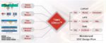
“By leveraging the scalability of cloud-based design environments, the IFS Cloud Alliance will enable broader access to Intel’s advanced process and packaging technologies. Our partnerships with leading cloud providers and EDA tool suppliers will provide a flexible and secure platform where customers can scale compute requirements instantly on production- proven design environments in the cloud.” Randhir Thakur, president of Intel Foundry Services
“We are excited to be collaborating with Intel in the launch of the IFS Cloud Alliance. We share a common goal to make semiconductor design and verification more scalable, and more accessible to a wide range of design teams, with the security and performance needed for reduced IC time-to-market and increased quality.” David Pellerin, director of Semiconductor Industry Solutions, Amazon Web Services
“Our close collaboration with Intel Foundry Services has brought together advanced node manufacturing with cloud computing and collaboration technologies, to establish a foundation for the next round of growth in the semiconductor industry. By joining Intel Foundry Services’ Cloud Alliance, Microsoft is proud to expand on that collaboration to provide a secure and scalable path to advanced silicon manufacturing. This is the latest chapter in the partnership between Intel and Microsoft that stretches back more than 40 years.” William Chappell, CTO, Mission Engineering, and vice president, Mission Systems, Microsoft Corp.
“Ansys’ comprehensive suite of interoperable, scalable multiphysics solutions plays a key role in IFS’ first design flow supported in the cloud. We look forward to continuing our long-standing collaboration with Intel to advance semiconductor design by ensuring that chip designers can access Ansys’ gold standard multiphysics solution via the cloud regardless of their chosen EDA workflow.” John Lee, vice president and general manager of the Semiconductor, Electronics, and Optics Business Unit, Ansys
“Cadence has longstanding leadership providing EDA solutions in the cloud and has successfully enabled thousands of customers to accelerate their innovation with our proven cloud solutions. Using the industry-leading, production-proven Cadence Cloud portfolio, which features highly flexible business models, customers have increased engineering productivity, significantly decreased turnaround times and improved overall cost efficiency. By joining the Intel Foundry Services Cloud Alliance, we’re enabling our mutual customers to leverage the scalable compute power of the cloud with our production-proven portfolio along with Intel’s advanced process and packaging technologies in a secure design environment.” Mahesh Turaga, vice president, Cloud Business Development, Cadence
“Siemens EDA has been optimizing tools for large-scale compute environments for more than 15 years. As part of the IFS Cloud Alliance ecosystem, Siemens EDA will work closely with cloud vendors, customers and Intel Foundry Services to leverage that experience to simplify the path to higher quality of results in less time. Siemens EDA is pleased to join the IFS Cloud Alliance ecosystem, and we look forward to extending the benefits of our industry-leading products and services to companies of all sizes who use Intel’s manufacturing services.” Craig Johnson, vice president, EDA Cloud Solutions, Siemens EDA
“Chip design is moving to the cloud at lightning speed. The Intel Foundry Services Cloud Alliance program will further accelerate the semiconductor industry’s adoption of cloud-based design, ensuring that engineers can continue to use the best technology, tools and flows as they move design to the cloud. We are collaborating with IFS as part of the Cloud Alliance, to enable our mutual customers to deploy our tools quickly and efficiently on the public cloud and help them deliver better products faster while meeting increasingly complex design and verification challenges.” Sandeep Mehndiratta, vice president, Enterprise Go-To-Market & Cloud, Synopsys.
Also read:
An Update on In-Line Wafer Inspection Technology
0.55 High-NA Lithography Update

