

Dosing for EUV lithography walks a fine line between productivity and defectivity. Fabs can choose higher-dose exposures to suppress photon shot noise [1]. However, higher doses require EUV machines to scan the wafer at slower speeds, degrading throughput [2].
On the other hand, there is the threat of resist thickness loss that increases with dose, due to correspondingly increased exposure to the EUV-induced hydrogen plasma [3-5]. Now, there is accumulated data indicating that, even without considering the EUV-induced plasma, the EUV exposure itself degrades the resist, as evidenced by outgassing, even before the resist is developed.
IMEC studied the outgassing for an environmentally stable chemically amplified photoresist (ESCAP) as a function of dose using photoemission spectroscopy (PES) [6]. At a dose as high as 200 mJ/cm2, the PES spectra shows a visible difference from the unexposed case. X-ray photoelectron spectroscopy (XPS) measurements showed that the photoacid generator (PAG) contains a fluorine-containing anion that outgasses significantly during EUV exposure, increasing as a function of dose (Figure 1).

Figure 1. Loss of fluorine from ESCAP as a function of exposure dose, as measured by XPS [6].
30% of the fluorine was lost at a popularly targeted dose of 60 mJ/cm2. This represents significant PAG degradation that occurs during EUV exposure. This degradation is known to cause an increase in line edge roughness with higher dose, because acid generator concentration decreases with higher dose, decreasing the acid image contrast [7].
The outgassing increase with higher dose has also been observed in other resist platforms targeting higher EUV absorption as well. In particular, again using XPS, more than 20% carbon loss was detected at 100 mJ/cm2 in tin-based EUV photoresists studied by a group headed by the University of Amsterdam (Figure 2).
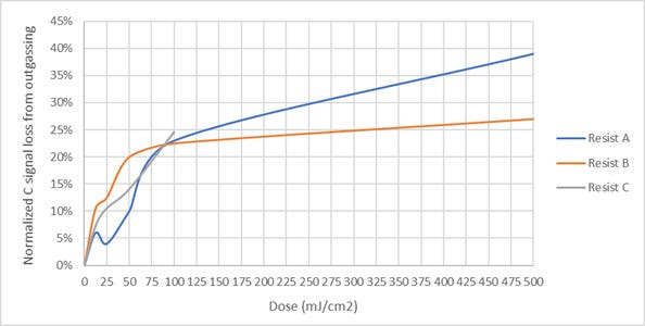 |
Figure 2. Loss of carbon from tin-based EUV resists as a function of exposure dose, as measured by XPS [8].
Even at a moderate dose of 50 mJ/cm2, the carbon loss in these tin-based resists is already at least 10%! The carbon loss or displacement could correspond to losses in solubility in developer [8]. Therefore, resist degradation by EUV exposure is a fundamental issue that must be considered carefully in the context of increasing absorbed dose to control EUV stochastics [1].
References
[1] C. Mack, Stochastics: Yield-Killing Gap No One Wants to Talk About.
[2] I. Fomenkov et al., Adv. Opt. Techn. 6, 173–186 (2017).
[3] Y-H. Huang, C-J. Lin, and Y-C. King, A study of hydrogen plasma-induced charging effect in EUV lithography systems (2023).
[4] F. Chen, Resist Loss Prohibits Elevated EUV Doses (2025).
[5] F. Chen, Resist Loss Model for the EUV Stochastic Defectivity Cliffs (2025).
[6] L. Galleni et al., Proc. SPIE 13428, 134281D (2025).
[7] T. Kozawa, Jap. J. Appl. Phys. 51, 06FC01 (2012).
[8] Q. Evrard et al., Proc. SPIE 12498, 124980Z (2023).
This article originally appeared in Substack: EUV Resist Degradation with Outgassing at Higher Doses
Also Read:
IMEC’s Advanced Node Yield Model Now Addresses EUV Stochastics
Edge Roughness Differences Among EUV Resists
Edge Roughness Differences Among EUV Resists
Share this post via:


Musk’s Orbital Compute Vision: TERAFAB and the End of the Terrestrial Data Center