For a leading-edge lithography technology, EUV (extreme ultraviolet) lithography is still plagued by some fundamental issues. While stochastically occurring defects probably have been the most often discussed, other issues, such as image shifts and fading [1-5], are an intrinsic part of using reflective EUV optics. However, as long as these non-stochastic issues can be systematically modeled, effectively as aberrations, corrective approaches may be applied.
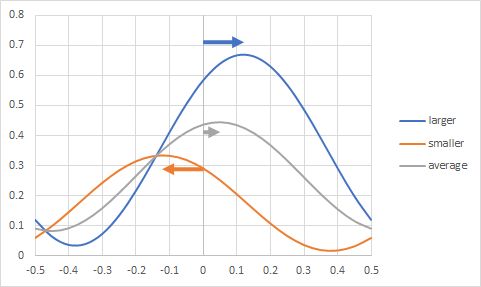
Image shifts are an unavoidable part of EUV lithography for a variety of reasons, including feature position on mask and mask position [6]. However, at any given position of and on the mask, image shifts occur because the image is actually composed of sub-images from smaller and larger angles of reflection from the EUV mask. The larger angles are generally smaller amplitude and shift one way with defocus, while the smaller angles are generally larger amplitude and shift the opposite direction with defocus. The combined effect is to have a small net shift with defocus (Figure 1). If the amplitudes for the smaller and larger angles were the same, there would be no shift [3].

The measured shifts and the best focus position are both nontrivial functions of both the illumination angle and the pitch [1]. From Figure 2, based on these measurements on a 0.33 NA system, we can also pick out illuminations which are best suited for particular pitches.

For example, the 32 nm horizontal line pitch is best matched with the 0.8/0.5 dipole shape (45 deg span, 0.5 inner sigma, 0.8 outer sigma). On the other hand, the 0.7/0.4 dipole shape seems best matched with around 37 nm horizontal line pitch, or closer to 37.3 nm. So, ideally, a pattern containing these two pitches should be printed in two parts, one with 0.8/0.5 illumination for the part containing 32 nm pitch, and one with 0.7/0.4 illumination for the part containing 37.3 nm pitch. This would solve both the best focus difference and defocus image shift issues for these two pitches.
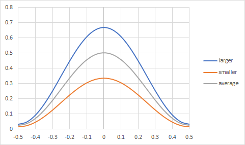
However, one other shift-related issue remains. The image position itself at best focus is different for different pitches. This can fortunately be corrected in a straightforward manner by the method suggested in Ref. 4. The shift can be directly compensated as different exposure positions. Moreover, the fading can be further eliminated by splitting the dipole illumination up as two exposures, one for each monopole [4]. This allows the perfect overlap of the images from each of the two poles (Figure 3). This would mean a total of four exposures for the 32 nm and 37.3 nm pitches. In addition, overlay needs to be tight for the shifts to be cancelled (<1nm). The dose would be reduced to 1/4 of the original dose for each exposure. However, the throughput may still suffer from the lower pupil fill (<20%) of the monopole. One alleviating possibility is to expand the monopole width to increase pupil fill, at least for some of the pitches being targeted.

This multiple exposure approach can be generalized to two-dimensional patterns, covering more pitches. In combination with mask position and mask position-dependent adjustments, it is the only true rigorous way to fully correct the image shift aberrations in EUV lithography.
References
[1] F. Wittebrood et al., ““Experimental verification of phase induced mask 3D effects in EUV imaging,” 2015 International Symposium of EUVL – Maastricht.
[2] T. Brunner et al., “EUV dark field lithography: extreme resolution by blocking 0th order,” Proc. SPIE 11609, 1160906 (2021).
[3] F. Chen, “Defocus Induced Image Shift in EUV Lithography,” https://www.youtube.com/watch?v=OXJwxQK4S8o
[4] J-H. Franke, T. A. Brunner, E. Hendrickx, “Dual monopole exposure strategy to improve extreme ultraviolet imaging,” J. Micro/Nanopattern. Mater. Metrol. 21, 030501 (2022).
[5] J-H. Franke et al., “Improving exposure latitudes and aligning best focus through pitch by curing M3D phase effects with controlled aberrations,” Proc. SPIE 11147, 111470E (2019).
[6] F. Chen, “Pattern Shifts in EUV Lithography,” https://www.youtube.com/watch?v=udF9Dw71Krk
This article first appeared in LinkedIn Pulse: Multiple Monopole Exposures: The Correct Way to Tame Aberrations in EUV Lithography?
Also Read:
ASML – Powering through weakness – Almost untouchable – Lead times exceed downturn
Application-Specific Lithography: Sub-0.0013 um2 DRAM Storage Node Patterning
Secondary Electron Blur Randomness as the Origin of EUV Stochastic Defects
Share this post via:


Website Developers May Have Most to Fear From AI