The data center rack server market is estimated to growat a high Compound Annual Growth Rate (CAGR) of 20% to reach $90 billion by 2021. Such growth is due to the significantly rise in the number of connected devices, the growth in the volume of data per device and theneed for quick processing of high-volume data. Much of these data travels through an Ethernet port and this is the driver for the development of the 25G high-speed Ethernet standard and its associated standards.
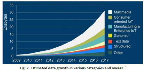
Prior to the introduction of 25G Ethernet, manufacturers had to build 40G or 100G by using 10G lanes, 10 lanes of 10G to reach 100G. The introduction of the 25G lane speed provides a scalable path to 100G while achieving significantly improved bandwidth when compared to 40G Ethernet. The picture below is extracted from a report by Cisco and clearly shows the exponential nature of the volume of data growth.

I have frequently written about interface protocols, from PCI express or USB to MIPI, highlighting how important it is to manage the development of the physical layer (the PHY) based on aserializer/deserializer (SerDes). Just a reminder, the PHY layer is made of three logical parts, the PCS (Physical Coding Sublayer), the PMA (Physical Medium Attachment Sublayer) and the PMD (Physical Medium Dependent Sublayer).
For most of the protocols, the IP vendor will deliver the PHY up to the interface with the controller, including the PCS, the PMA and the PMD, and the MAC (Media Access Control Sublayer) will be integrated in the controller IP. Except for the Ethernet protocol! Instead of two components (PHY/PCS and Controller) the vendor(s) will market three blocks: the MAC, the PCS and the Ethernet PHY (including the famous SerDes). In fact, the vendor may decide to integrate the MAC and the PCS together, but the PHY will stay apart. The split for Ethernet IP is based on the nature of the design (analog or digital) more than on logical layers.
Synopsys propose the DesignWare Enterprise MAC, which can be easily integrated with the Synopsys PCS layer. This PCS IP is compliant with the IEEE 802.3 and consortium specifications for 1G, 10G, 25G, 40G, 50G and 100G Ethernet PCS layers. When using the 25G PHY, the PCS supports various interfaces including single 25G, 2x25G for 50G Ethernet, and 4x25G for 100G Ethernet. Some of the key optional modules include the Read Solomon Forward Error Correction block (RS-FEC), link training support, and auto-negotiation.
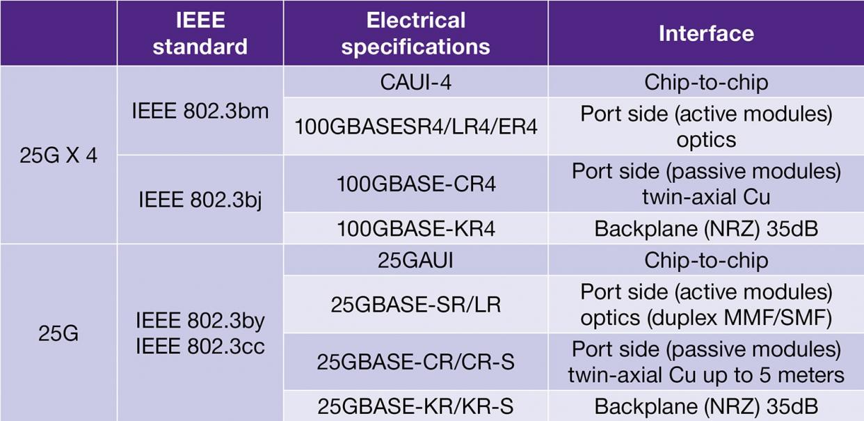
Based on the Consortium’s initial work, IEEE standards for 25G Ethernet are now defined in both single lane and 4 lanes of 25G. The Table below shows IEEE standards associated with 25G Ethernet with related electrical specifications.

The Enterprise MAC and PCS integrates seamlessly with the DesignWare Multi-Protocol 25G PHY IP. The configurable transmitter and receiver equalizers enable customers to control and optimize signal integrity and at-speed performance, and the continuous calibration and adaptation (CCA) provides robust performance across voltage and frequency variations. For data center applications, the signal integrity and the jitter performances have to be outstanding to comply with a very low bit error rate (BER) and the power should be kept as low as possible with support for Energy Efficient Ethernet (EEE).
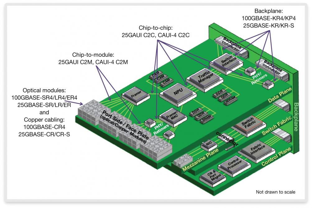
The 25G Ethernet standard supports various hardware interfaces such as chip-to-chip, chip-to-module and backplane. Chip-to-chip and chip-to-module at 25G significantly improve the overall system performance, while backplane Ethernet supports the evolving blade server market specifically moving from 1G to 10G and now 25G.
The figure below shows how 25G Ethernet can be used to both drive interconnect between the different chips/modules as well as the connection for modules via passive or active cables at the port side. It also shows the various implementations of the 25G Ethernet standards: single lane 25G Ethernet, 2x25G for 50G Ethernet or a 4x25G for 100G Ethernet. This flexibility gives designers a powerful set of interfaces that can be used in applications ranging from the switch fabric, traffic managers, and as interconnect to other modules in the server.

The 25G Ethernet standard is the new standard for connectivity in the data centers. The specification allows for transmission of more data in less time, and supports multiple hardware interfaces to give designers flexibility in designing their SoCs for various high-end computing applications
This standard, initiated by the 25G/50G Consortium and now by the IEEE, is expanded to a robust set of published and approved standards as part of IEEE 802.3. You can find papers describing the 10G Ethernet standard written as early as in 1999 (by the IEEE 802.3 High Speed Study Group, June 1, 1999). There is no doubt that the next standard coming after 25G, or the 50G Ethernet, will be released far much faster than the time it took to move from 10G to 25G. The need for quick processing of high-volume data is still growing exponentially!
By Eric Esteve from IPnest
More about DesignWare Ethernet Solutions: Synopsys’ complete Ethernet 25G solution
Share this post via:


Comments
There are no comments yet.
You must register or log in to view/post comments.