The development of the Unified Power Format (UPF) was spurred on by the need for explicit ways to enable specification and verification of power management aspects of SoC designs. The origins of UPF date back to its first release in 2007. Prior to that several vendors had their own methods of specifying power management aspects of a design. The IEEE 1801 specification that emerged has become widely accepted by designers and EDA tools that are related to power. Each new revision of the IEEE 1801 specification has worked to clarify and improve the effectiveness of UPF.
Yet, with such a novel and comprehensive scope, ideas that initially seemed workable have shown to have weaknesses. The very fact that there is no guarantee of backwards compatibility between revisions of IEEE 1801 shows that the working committee is willing and able to update and improve aspects of the specification that experience has shown need to be changed. One such area that was highlighted during a presentation at the 2022 DVCon by Progyna Khondkar from Siemens EDA. His paper and presentation titled “Path Based UPF Strategies Optimally Manage Power on Your Designs” clearly and concisely covers the changes in 3.0/3.1 relating to strategies for UPF protection elements such as isolation, level shifters and repeaters.
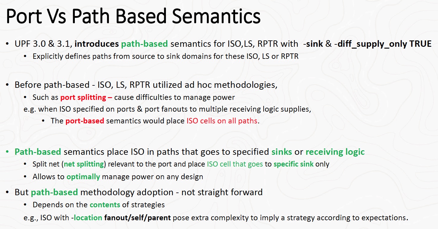
Previously the UPF syntax and semantics used to specify the location of isolations, level-shifters or repeaters, which are used between power domains to ensure proper operation of the circuit, were ad hoc and port based. In specifying the location of these protection elements or cells, there are a few kinds of potential problems that can arise – failure to insert a needed element, incorrect insertion of an element or duplicate placement of an element. The expansion in semantics from port based to path based is a significant change that addresses all of these issues.

UPF has added explicit use of -sink and -diff_supply_only TRUE to control inferring UPF protection cells. This is coupled with new precedence rules to eliminate unnecessary cells. Previously port based semantics allowed port splitting, which led to redundant UPF protection cell insertion. Now port-splitting is an error. UPF protection elements can be placed along a net so that only connections to specified sinks are made. This leads to the placement of UPF protection elements as close to the sink domain as possible.
There are a lot of nuances to this change in UPF. The Siemens paper and presentation do an excellent job of going through various scenarios to illustrate the effects of using various path based options, while also comparing them to how port based semantics would perform.
There are three context options that can be used for UPF protection elements: -location self, -location parent and -location fanout. They have a profound effect on protection element placement. At the same time, they allow very precise tuning of this placement and remove ambiguity – leading to more precise results. The Siemens paper goes through each of them with illustrative examples to show how they differ. There is also a comparison of how the effects of the location directives are influenced by the choice of port or path based semantics.
There is a lot to absorb with this change. Tools supporting path based UPF protection elements need to perform consistently and also issue meaningful warnings when there are going to be unexpected results. The author suggests an approach for this. The paper and presentation conclude with a number of caveats and suggestions for designers switching to path based semantics. However overall it looks as though this is a welcome addition that will improve design quality and verification efficiency. The paper and presentation are available at the DVCon 2022 website.
Also read:
Co-Developing IP and SoC Bring Up Firmware with PSS
Balancing Test Requirements with SOC Security
Siemens EDA on the Best Verification Strategy
Share this post via:


Comments
There are no comments yet.
You must register or log in to view/post comments.