
This article is an abstract of Paul Clewes’ webinar you can find here.
Differential amplifiers apply gain not to one input signal but to the difference between two input signals. This means that a differential amplifier naturally eliminates noise or interference that is present in both input signals. Differential amplification also suppresses common mode signals. In other words, a DC offset that is present in both input signals will be removed, and the gain will be applied only to the signal of interest. In most real-world applications, the differential pair is connected to a current mirror or an active load. This vastly decreases the amount of silicon area that is required and greatly increases the gain.
The differential pair in analog layout is all about balance. Therefore, for optimal performance, its MOSFETs must be matched. This means that the channel dimensions of both MOSFETs must be the same, and the routing should be balanced. Any difference in the parasitics of the left and right sides of the differential pair will reduce its performance.
We can easily demonstrate all these layout concepts using a traditional schematic editor and a plugin provided by Pulsic. Pulsic’s plugin is called Animate Preview and generates a DRC clean layout for an analog circuit that is loaded into a schematic editor. Animate runs in the background and automatically recognizes key structures like differential pairs and current mirrors. It also automatically constrains the placement to generate a human-quality placement, including differential pairs.
Animate creates multiple layouts for your circuit and shows the layout directly inside your traditional schematic editor.
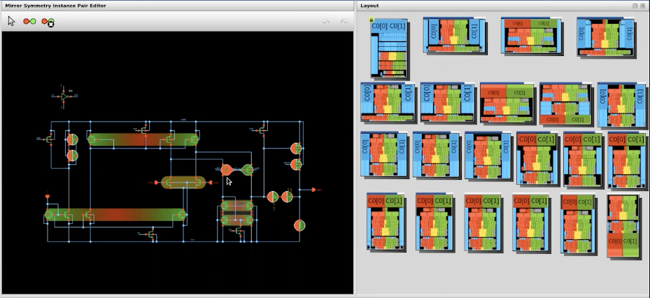
Here is an image showing the Animate Preview plugin window. On the right-hand side of the window, we have numerous automatically generated layouts. All of these layouts are for this one schematic. At the bottom, we have the constraints. These constraints are all automatically generated by Animate. And on the left-hand side, we have some stats for each of the generated layouts.

Animate’s multiple initial layouts can be seen on the right-hand side.

Clicking a differential pair will highlight its position in the layouts.
We can see that Animate has automatically detected the differential pair for us, and it has drawn a halo around the two devices in the differential pair directly on the schematic. If we look at the constraints options, we can see that animate has recognized these two devices as being a differential pair, and it has automatically constrained the layout of those two devices to balance the routing within the differential pair and see if it’s possible to generate a cross quad layout. Let’s have a look at one more option, that’s the number of rows. Animate will automatically consider one, two, three, and four-row counts for the devices in this particular differential pair.
Animate will consider all of the different options and work out the permutation that generates the best differential pair layout, considering the requirements of that differential pair and the context in which it is in. Once Animate generates the constraints, the next step is to generate the layouts, which are then shown on the right-hand side of the screen. If we select the differential pair in the schematic, we can cross-probe into the layout.
We want each device of the differential pair to have the same geometrical environment because that means that any process variation or LD effects on the devices can be balanced out. The first step to achieve this is for Animate to place these devices in a regular grid. The second step is that all of the spacings around the differential pair should be identical. So when we look at horizontal spacing, the gap between devices should also be identical. In this case, we’ve only got two rows. If we have more than two rows, then we would want all of those gaps to be identical so that each of the active devices in our differential pair has exactly the same geometrical environment.

Upon selecting our differential pair, we can cross-probe it into the layout.

Polyheads are indicated with little yellow arrows.
In terms of the geometrical environment, we also want the devices to have the same neighbors on the left and the right. In order to achieve that at the end of the rows, Animate has inserted dummy devices for us. These are the light grey devices in the image. These have been automatically inserted by Animate because animate recognizes that we have a differential pair. We also want the poly heads to be identical. If you look closely, you can see the poly head direction is marked by a small circle. All of the devices on the top row have the poly head on the south side, and all of the poly heads on the second row are on the north side of the device.
In order to make sure that each of these devices behaves identically and to counteract process variation across the die, Animate is going to deploy a common centroid layout if possible. If we select just the left-hand device in the schematic, we can see it is straddled, and the second device has got the opposite diagonal, and this means that the average position of those devices is exactly the same. The average position is in the center. In other words, they have a common center of gravity or common centroid. Further than that, thinking ahead in terms of the routing, we want the routing to balance, and therefore Animate has used a cross-quad pattern. Cross-quad is a common centroid by nature, but by having a cross-quad, Animate also has the opportunity to balance the routing, which we’ll see next.

Cross quad common centroid design.

Adding dummy devices to our layout.
We can be reasonably happy with this automatically generated differential pair layout, but there are a few aspects that could be improved. Let’s say we are happy with the horizontal matching that Animate achieved. But vertically, we can see the devices are not matched. The north edge of this device is next to the guard ring. The south edge is also next to the guard ring, but there is a gap. These aren’t not vertically matched yet. This plugin allows us to modify that matching. There are a couple of different ways in which we might want to do that for differential pair. The first option is to add additional rows of dummies above and below the device. We can do that inside Animate using its drag-and-drop interface. We simply select where we want devices, and we can easily add two rows of dummies. And unlike a traditional layout editor, Animate’s editor allows us to not only control the structure of the layout but also it will automatically take care of all of the DRC rules for us. After the process completes, we’ll be back to a DRC clean routed differential pair but with the additional dummies.
Now we have the horizontal matching that we had before and the vertical matching of each device. Animate includes options to reduce the width of these dummy devices if that’s appropriate for your PDK. You can also increase the finger count of the end-of-row dummies. In the example, it is reduced to a single finger, but you can specify an option to say I want the same finger count as the active devices.
An alternative to adding the dummies is to instead have the same guarding reinforcement on each side of the devices, and this can also be done inside Animate’s drag-and-drop editor as well. We can do that by first selecting the guard ring, and we will be presented with numerous anchor points. We then draw reinforcement between any of these anchor points. Animate will again redo the routing and get us back to a DRC clean layout.
Now onto the routing. We are going to use the detailed view so that we can see the routing that animate has considered. We have two objectives with the routing of the differential pair. First, we want any metal that’s above or around the active areas of the devices to be identical. Secondly, we want the parasitics of the left and the right-hand side of the differential pair to be balanced to be the same.

We can use the drag-and-drop tool to draw new guard rings.

Metal one layer is identical on both devices.
We don’t mind so much about what those parasitics are, but we do want them to be balanced. Let’s start by looking at whether the metal is identical for each of the moves. This is the poly for our differential pair, and by cycling through the layers, we can see that metal one, metal two, and metal three for this device are exactly the same.
On metal four is the first we see any routing going over the top of devices, but where we have it gone over the top of devices, the metal is exactly the same for each one of the active devices. Animate has achieved the first objective for a differential pair. Making the metal for each unit to be exactly the same in each of the metal layers.
The next requirement is to balance the routing. So we want the two inputs on the left and the right to balance, and we want the internal routing of the drains to balance. We want the parasitics of those to be identical, and the easiest way to do this is to have identical geometry for both the left and right sides.

The routing on metal four is the same for all the active devices.

We can see the connections on the second and third metal layers.
Now let’s look at the gate connections. These are routed on the second and third metal layers. We can see the cross-quad connections, we can’t exactly match the same layers because we would get a short, but we can see what Animate has done here. By selecting each of the gates, in turn, we can see that the routing is on different layers, but the geometry is identical, width the same width and length, and therefore those two nets are as balanced as they can be.
Ok so, we’ve balanced the parasitics within the differential pair. But the parasitics balancing should not be contained simply within the differential pair. We should also balance what differential pair is connected to as well. And the most common topology is for the differential pair to be connected to a current mirror.
The current mirror has its own matching requirements. We’re trying to make the two legs of the current mirror match the reference. In this case, the diode has been placed in the middle, and the two legs have been placed diagonally around the outside of the diode so that the current mirror itself achieves a common centroid layout. Moreover, Animate is thinking about the interactions between the current mirror and the differential pair. We can see that the tool has arranged the differential pair and the current mirror so that they have a common line of symmetry. They have also been arranged in such a way that the routing is as straightforward as possible between those two structures. In this circuit, M10 connects to M20, and M11 connects to M19, so we can see here that the bottom row current mirror lines up with the top row of the differential pair, and therefore the routing will be as straightforward as possible.
Obviously the particular patterns you need depends on where the current mirror is placed in association with the differential pair. There’s no point coming up with the perfect differential pair layout in isolation because it really does depend on what it’s placed with and where.

Detailed view of the current mirror and differential pair routing.
Here is a high-level view of the placement of the differential pair and its current mirror. Looking at the parasitics from the differential pair and the current mirror, if we select the first leg, we can the routing on the right-hand side here between the current mirror and the differential pair, and if we select the other leg, we can see that it has got the identical symmetrical, balanced shape. The parasitics are not only balanced within the differential pair structure but also between the differential pair and the current mirror. This means the entire structure is balanced.
Okay so so far we’ve just looked at the differential pair and the current mirror, but you might ask if there is additional wiring over to other devices shouldn’t we balance the parasitics of those as well so the entire structure is balanced?
A common way of achieving that requirement is to generate a butterfly-style layout with a vertical line of symmetry. We would then have a left-hand side that exactly mirrors the right-hand side. To achieve this, a common technique is a half-cell where you put half of the devices into one circuit you lay out on the left-hand side and then copy, paste and flip to generate the right-hand side. In Animate, that can be achieved directly without having to generate a half-cell. We can do that by going to the style tab and selecting the mirrored base analog style.
For this style of layout, Animate requires some additional information, it needs to know which of the devices should be on the left-hand side and which devices should be on the right-hand side of the mirror symmetry. However, as with Animate’s other constraints, you don’t need to enter that information manually. Animate will attempt to generate that data automatically and then display it with these red and green colors on the schematic.

Animate style tab for your schematic.
There are various indicators here: a red teardrop means that the device is going to be placed on the left-hand side of the mirror symmetry and a green teardrop means that the device is going to be placed on the right-hand side. These teardrops are joined to indicate that they are symmetric partners. We also have two semicircles; what does that mean? Well, that means that we have an M-factor device and we want to place half of the M-factor on the left and half on the right-hand side. You can see that same symbol on top of the resistors, despite having an M-factor of one. Animate will actually split the resistors into two for us so that the halves can be placed symmetrically. You will note that the match structures have their own color because matches have their own internal symmetric requirements. Animate has now generated numerous new layouts in this new style. If we select the differential pair in the schematic you can see that the differential pair has been placed in the middle on the vertical line of symmetry and then the other devices are radiating away from that central area so that each of the parasitics on on the left are balanced to those on the right for the block. Animate has automatically achieved a butterfly-style layout.
Summary
For optimal differential pair performance:
- Channel dimensions of both MOSFETs must be the same.
- Placement should be matched, considering LDEs.
- Metal should be identical for every MOSFET unit.
- Routing should be balanced (R&C) within the differential pair.
- Routing between current mirror and differential pair should also balance.
- Balancing for the entire block can be achieved with butterfly layout.
- With the differential pair placed on a vertical line of symmetry.
Also Read:
Freemium Business Model Applied to Analog IC Layout Automation
Analog IC Layout Automation Benefits
Obtaining Early Analog Block Area Estimates
CEO Interview: Mark Williams of Pulsic
Share this post via:


Comments
There are no comments yet.
You must register or log in to view/post comments.