
The Accellera organization created the concept of a Unified Power Format (UPF) back in 2006, and by 2007 they shared version 1.0 so that chip designers would have a standard way to communicate the power intentions of IP blocks and full chips. By 2009 the IEEE received the Accellera donation on UPF , reviewed multiple drafts and published IEEE Std 1801-2009, also known as UPF 2.0. In 2013 the IEEE updated it to 1801-2013, or UPF 2.1. Updates to UPF continued into 2015 and 2018 as well.
Why do we even need UPF?
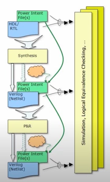
RTL languages like VHDL and SystemVerilog don’t include the notion of power intent, just logic functionality, so something needed to be added for power intent. Here’s an EDA tool flow showing where power intent files are used during design, verification and even implementation:
Source: IEEE
What’s Inside a UPF File?
Power intent is defined using an extension of the Tool Command Language (Tcl) and has the following components:
- Power Domains
- Power Supply Network
- Power State Table
- Isolation Strategies
- Retention Strategies
- Level Shifter Strategies
- Repeater Strategies
Who Creates UPF Files?
Your IP vendors supply RTL code, and constraint UPF file, then your design team adds a configuration UPF file for the specific context. Implementation-specific UPF files are also added along the way, so the EDA tool flow becomes:

How about using Hierarchy?
UPF supports both flat and hierarchical descriptions, and in general it’s recommended to align power domains with your logic hierarchy to keep life simple. If you choose to implement your design from the bottom-up, then ports need to be added in your UPF descriptions.
In a traditional bottom-up methodology an engineer would read all of the UPF files, then start manually editing each UPF file to ready them for merging into a top file. The UPF top-level file would be manually created, with care made to verify that proper syntax was typed. The power rules would also be verified before and after promotion.
Here’s a diagram showing a simple chip design example with four instances, named A, B, C, D; and at the top-level you can describe this with either hierarchy (left side), or as a flat design (right side):

With the hierarchy example on the left, we have five UPF files, while in the flat example on the right only one UPF file. Switching between using UPF hierarchy or flat is called promotion or demotion, and as you can imagine involves some detailed Tcl editing. Sure, you could manually do these operations and hope that you got all of the edits correct, or you could use an EDA tool designed for this purpose.
Going from a single, flat UPF file to a hierarchical collection of UPF files is called demotion, and once again, there is manual editing required. If any RTL code is modified during this process, then that adds more UPF file editing.
Thanks to EDA vendor Defacto Technologies we now have such an EDA tool to manage jointly UPF and RTL pre-synthesis through SoC Compiler. During the front-end SoC build process a design team has many files to manage, and SoC Compiler enables an engineer to quickly work with RTL, IP-XACT, UPF and SDC files.
With SoC Compiler an engineer can easily manage power-intent hierarchy, out of the box, with two simple APIs: promote_power_intent, demote_power_intent. Typical applications where UPF promotion and demotion are used in a project include:
- When exporting an IP block from an SoC for reuse
- Integrating multiple IPs into an SoC
- Using hierarchical synthesis
Summary
They say that necessity is the mother of invention, and the development team at Defacto has taken a look at how the UPF standard came about, and noted that processes like promotion and demotion to work with hierarchy has required far too many manual, error-prone editing steps. Their UPF automation embodied in the SoC Compiler tool provides much-needed relief to SoC teams by quickly using UPF promotion or demotion.
Webinar
There’s a March 10th webinar from 10AM to 11AM PST all about SoC Compiler from the team at Defacto Technologies, so sign up here.

Related Blogs
- Webinar – How to manage IP-XACT complexity in conjunction with RTL implementation flow
- WEBINAR: What Makes SoC Compiler The Shortest Path from SoC Design Specification to Logic Synthesis?
- Small EDA Company with Something New: SoC Compiler
- CEO Interview: Dr. Chouki Aktouf of Defacto
- Power in Test at RTL Defacto Shows the Way


Comments
There are no comments yet.
You must register or log in to view/post comments.