The three F’s of electronic product development are: form, fit, and function. Although the F/F/F assessment typically refers to the selection of the right component, it most definitely also refers to the selection of the proper cabling between assemblies. The requirements for cables are varied, and demanding: ability to provide optimal signal transmission impedance and shielding, flexibility, lightweight, resistance to vibration, reliability and material stability (especially when subjected to environmental extremes and repetitive flex motion), ease of manufacturing assembly, and, compatible with the constraints of the product enclosure (e.g., suitable for difficult contours, minimal perturbation to airflow, etc.).
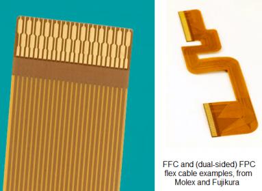
For over 60 years — longer than Moore’s Law — flexible flat cables (FFC) have been an attractive solution to the F/F/F demands for cabling. In its most basic implementation, the FFC is a composite of polyimide layers to which a set of metal wire connections have been adhesively bonded. A coverlay is bonded over the core layers to protect the metal. The adhesive coverlayer can be tinted, to give the FFC its characteristic amber or green color. The ends of the wires are exposed and tinned, for insertion into a connector. A stiffener layer is typically added at the ends of the cable to improve the assembly process. FFC’s have been a fundamental enabler for the computer and consumer electronics industries. (FFC’s have been on the moon, as part of NASA’s F/F/F strategy.)
Much as the IC industry has evolved to support an increasing number of signal interconnect layers, so too has the flexible cable technology evolved. Multiple polyimide and patterned metal layers in the composite are used to create complex interconnect topologies. Copper-plated through vias connect signals on different layers of the multi-sided flex cable. The multi-layer cable requires metal patterning/etching/via drilling/plating — these designs are often denoted as flexible printed circuits (FPC), due to their similarity to PCB manufacture.
Fast forward to the dramatic increase in the adoption of mobile and wearable products over the past decade. Product designs are increasingly stressing the minimization of volume and weight, the simplification of manufacturing assembly, increased product reliability, and (to be sure) final cost, all serving as critical product goals.
The FFC or FPC inserted into sub-assembly connectors no longer satisfies these requirements. An alternative implementation has emerged, and is now the preferred approach for a vast range of consumer, automotive, medical, and mil-aero applications — the rigid-flex assembly.
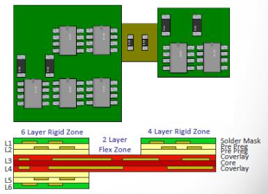
A rigid-flex design includes multiple PCB substrates for mounting components and connectors, and attachment to the product chassis/enclosure. The key differentiating feature for rigid-flex technology is the lamination of and electrical connectivity to a set of flex layers within the PCB substrate, as illustrated in the figure below. (Note that this example also illustrates the attachment of surface mount components to the flex cable, as well.)
I recently had the pleasure of chatting with David Wiens, Xpedition Product Manager at Mentor Graphics, about the tremendous growth in the rigid-flex market, and specifically, about the unique EDA tool requirements associated with this technology. I have to confess that I didn’t appreciate the difficulty in developing a rigid-flex asembly — David opened my eyes to the intricacies, and how features in the recent Xpedition Enterprise release have accelerated rigid-flex design productivity and quality.
Dave highlighted, “Rigid-flex design requires managing the complexity of the assembly across both electrical and mechanical domains. Designers need to work seamlessly across both 2D and 3D domains, to complete the physical (2D) implementation while maintaining a 3D flex perspective.” The figure below is a screenshot example from Xpedition, showing the two visual representations side-by-side.
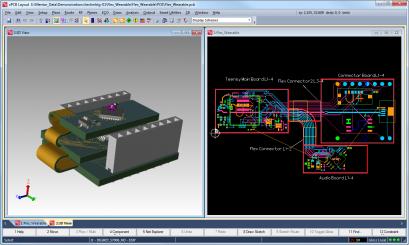
Another example of complexity management that Dave pointed out was the unique support required for maintaining multiple stack-up cross-sectional definitions for the various rigid board and standalone flex regions.

“The Xpedition design environment is integrated with our HyperLynx tool for signal and power integrity analysis. That collaboration is important, to ensure that the electrical characteristics of these complex stack-ups and material interfaces are extracted and simulated accurately.”, Dave emphasized.
An Xpedition Enterprise feature that is an absolute must for rigid-flex is the capability to define and exercise structural rules to apply to both the folded and unfolded assembly data. The rigid-flex manufacturer and design team will collaborate on rules for:
- component placement and folded clearance
- flex bend geometries, both for static bending and (especially) any repetitive dynamic flex motion
- no changing wire direction or vias present in the “flex zone” to eliminate micro-cracking
- smoothness of the bend
- the requirements at the rigid-flex interface for a stiffener
- no vias close to stiffener
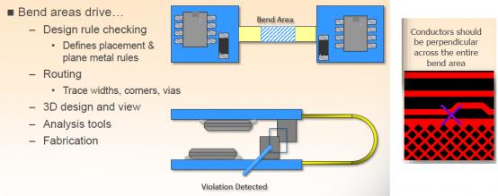
The 3D data representation enables accurate and thorough examination of these manufacturability rules. “Designers no longer have to build physical mock-ups of their assembly concept, and try to visualize rule violations.”, Dave highlighted.
Another unique requirement of flex design that Xpedition supports is the unique data representation for vias and wire arcs.
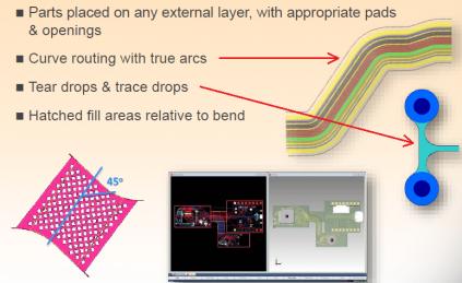
Dave informed me, “Metal arcs require true curve data formatting — attempts to represent the arc as a set of vectors will increase the risk of micro-cracking. Similarly, vias and T-junctions require teardrop traces around the geometry. Solid geometries require cross-hatching (with specific rules for hatching orientation in a flex zone). The automated layout features of Xpedition Enterprise have been enhanced to handle these unique requirements.”
As the rigid-flex assembly is linked to the product enclosure, electrical-mechanical co-design is required. Xpedition interfaces with mechanical MCAD design tools, using the STEP/ProSTEP data interchange format. Mentor has expanded the (de facto standard) ODB++ manufacturing data release format to include the necessary design constructs.
The emergence of new applications emphasizing product volume, flexibility, manufacturability, and cost has been enabled by advances in rigid-flex technologies. The latest release of Mentor’s Xpedition Enterprise provides support to visualize and analyze the complexity of the 2D unfolded and 3D folded assembly. The collaboration with HyperLynx enables accurate SI/PI analysis. The rules coding and checking support enables designers to ensure the manufacturability of intricate topologies. The data interfaces ensure consistency and collaboration with mechanical product co-design.
Much like Moore’s Law has described IC fabrication evolution over the past 50 years, so has flexible cable/assembly technology been an indication of the advances in electronic products. It will be enlightening to continue to follow the development of flexible electronics.
If a rigid-flex design is appropriate for your product, I would encourage you to check out the following link, with information on Mentor Xpedition Enterprise.
-chipguy
Share this post via:


Comments
There are no comments yet.
You must register or log in to view/post comments.