Many types of designs, including analog designs, MEMs, and image sensors, require electrically matched configurations. This symmetry has a huge impact on the robustness of the design across process variations, and its performance. Having an electrically matched layout basically means having a symmetric layout. To check the box of electric matching during verification, designers must also check the symmetry of their design.
Design symmetry is defined as either 1D or 2D. 1D symmetry is the symmetry around the x-axis or the y-axis, while 2D symmetry is the symmetry around the center of gravity.
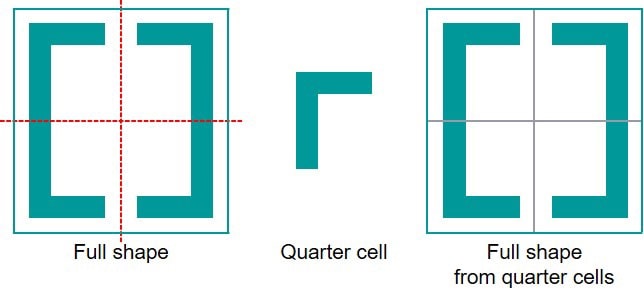
One approach to achieving 1D symmetry is the quarter cell method, in which a cell is placed four times around a common X and Y axis.
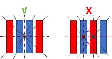
In 2D layout symmetry, there is a common centroid, and this common symmetry can be between multiple devices, or even groups of devices. Here’s an example of common centroid symmetry on the left, while the right side is not a common centroid:
You can just eyeball an IC layout to see if it’s symmetric, but that’s not precise at all. Another approach is to write specific rule checks, based on your design experience, to catch symmetry violations. A more scalable approach is to use the Calibre nmPlatform with one of three symmetry checking methods:
- Batch symmetry checks
- Calibre PERC reliability platform for electrically-aware symmetry checks
- A new approach that leverages the Calibre RealTime tools to allow for an interactive symmetry checking experience
Taking an interactive approach, which avoids custom rule coding and supports iterative runs to immediately check changes, can offer the highest accuracy and greatest time savings. This solution includes four kinds of interactive symmetry checks:
- 1D symmetry
- Symmetrical about X-axis
- Symmetrical about Y-axis
- 2D symmetry (aka common centroid)
- 90° symmetry
- 180° symmetry
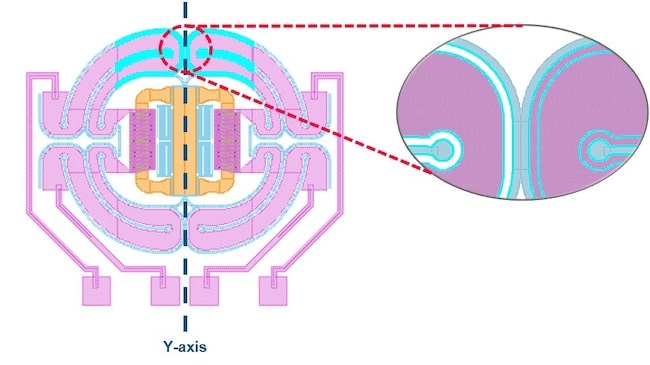
With Calibre’s interactive solution, the symmetry checks give live feedback to pinpoint any violations for fixing, and DRC checks can also be run in parallel to add even more efficiency. An example of the graphical feedback is shown for a magnetic actuator, where the metal layer on the right of this MEMS circuit has a symmetry violation highlighted in cyan color:
Verifying that two devices in a differential-pair op-amp are symmetrical involves selecting the device area, running the symmetry check, and viewing the results to pinpoint any violations.
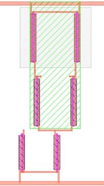
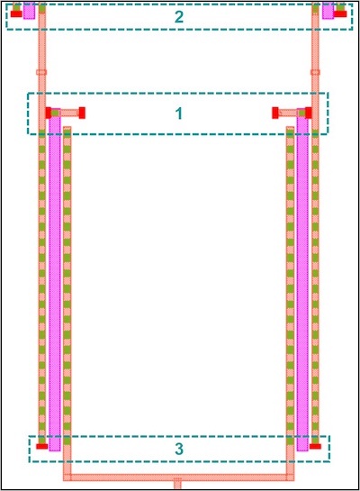
The error markers tell the layout designer where the symmetry violation is, and whether it is caused by missing or extra polygons, shifted polygons, or a difference in polygon size. Fixing symmetry violations may create new DRC violations, making it advantageous to run both kinds of checking (symmetry & DRC checks) at the same time to reduce the time needed to achieve a symmetric DRC-clean design, such as is possible with the Calibre toolsuite.
Summary
Analog IC layouts design can be a long, manual and error-prone process, leading to lengthy schedules, especially when symmetry is required to achieve optimum performance. Traditional approaches, like coding custom symmetry checks or doing visual inspections, can take up valuable time and resources.
The approach of using a commercial tool like the Calibre nmPlatform to perform interactive symmetry checking is a welcome relief. Because the interactive results happen so quickly, the layout designer is alerted to the specific areas that are violating symmetry rules and is then able to apply fixes, saving valuable time. Being able to check for both symmetry and DRC violations interactively is a nice combination to ensure a symmetric DRC clean design.
Read the complete white paper online here.
Related Blogs
- EDA in the Cloud with Siemens EDA at #59DAC
- Calibre, Google and AMD Talk about Surge Compute at #59DAC
- What’s New With Calibre at DAC This Year?
- AMS IC Designers need Full Tool Flows
- Methods for Current Density and Point-to-point Resistance Calculations


Comments
There are no comments yet.
You must register or log in to view/post comments.